Jump To:
AutoPole functionalitySupported connection types
Description of the AP20 ON/OFF button and status LEDs
PoleHeight
PoleHeight step-by-step
Tilt Compensation
Tilt Compensation step-by-step
TargetID
TargetID step-by-step
AutoPole functionality
Functionalities are listed according to the individual sales variants.
| Functionality | AP20 H | AP20 ID | AP20 T | AP20 |
| PoleHeight | ✓ | − | ✓ | ✓ |
| Tilt Compensation | − | − | ✓ | ✓ |
| TargetID | − | ✓ | − | ✓ |
☞ AP20 can only be used in combination with an AP Reflector Pole (CRP4, CRP5, GLS51 and GLS51F) or an AP Mini Pole (GLS53 or GLS54).
☞ Establish a Bluetooth connection between the AP20 and the field controller or the total station in order to be operative. Use the connection wizard.
Supported connection types
Supported
AP20 (all variants) with TPS
☞ A robotic TPS must be connected to a controller first. Then connect to AP20.
| Instrument | iCR80 | iCR80S | iCR70 | |||
| Handle | CCD6 | CCD18 | CCD6 | CCD18 | CCD6 | CCD18 |
| AP20 AP20 T |
− | ✓ | − | ✓ | − | ✓ |
| AP20 H AP20 ID |
✓ | ✓ | ✓ | ✓ | ✓ | ✓ |
TS16 and MS60 can also be used
Not supported
- AP20 (all variants) with GNSS (no PoleHeight)
- Onboard use case
Description of the AP20 ON/OFF button and status LEDs
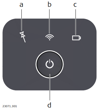
| a | Tilt Compensation LED |
| b | Connectivity LED |
| c | Power LED |
| d | ON/OFF button |
Description of the LED Indicators
| LED | LED Status | Status of the Instrument |
| Tilt Compensation LED |
off | Tilt compensation is unavailable or switched off. |
| green | Tilt compensation is activated, compensation values are stored. Tilt compensation is being applied to the point measurement. |
|
| red | Tilt compensation is activated, but currently not being applied to the point measurement. | |
| Connectivity LED |
off | AP20 is not powered or module is not ready. |
| green | Bluetooth is visible for other instruments and ready for connecting. | |
| blue | Bluetooth has connected. | |
| Power LED | off | Battery is not connected, flat or AP20 is switched off. |
| green | Power is 21% - 100%. | |
| red | Power is 11% - 20%. The remaining time for which enough power is available depends on the type of survey, the temperature and the age of the battery. |
|
| flashing red | Power is low (<10%). |
PoleHeight
The AP Reflector Pole can be extended to any of the given snap-lock positions in order to overcome obstacles.
As soon as a snap-lock position is reached, the attached AP20 receives the detected height from the AP Reflector Pole and transmits it to the field software of the connected total station or field controller.
The transmitted height corresponds to the current length between prism centre and pole tip, which is equivalent to the printed scale on the pole and the height input field within the field software.
☞ Valid height detection is limited to the snap-lock positions. Intermediate positions are indicated as invalid. Enter the height manually.
☞ Optional pole extensions are not taken into account.
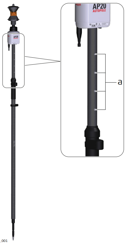
| a | Snap-lock positions |
PoleHeight step-by-step
PoleHeight is only supported with sales variants AP20 H, AP20 T and AP20.
PoleHeight can be used if the controller is connected to a robotic TPS instrument.
When using an AP20 T, an AP20 H or an AP20 make sure that AutoPole is selected as prism type.
- In any app:
Open the Controller/Target container from the status bar.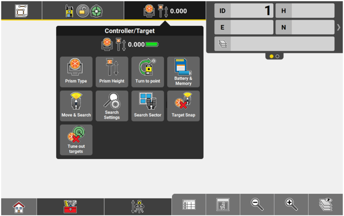
- Tap Prism Height.
- To turn PoleHeight ON:
Tap on the Auto height feature.
To turn PoleHeight OFF:
Select any predefined height or enter the height manually.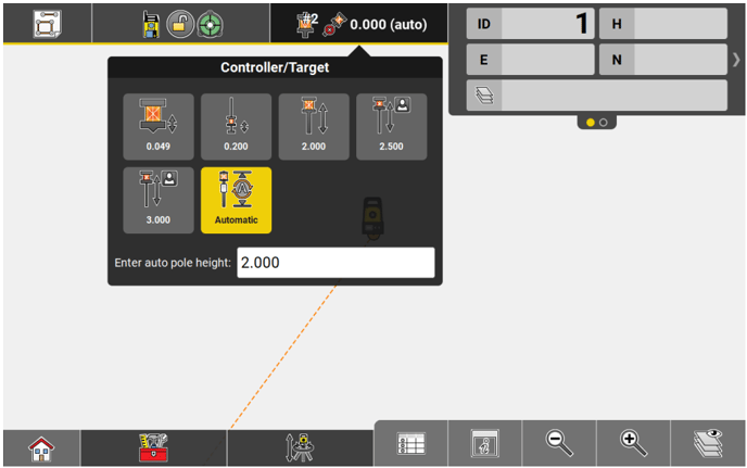
- Extend or compress the pole physically to overcome obstacles.
- If Auto height is used, the correct value is displayed in the status bar.

- Measure or stake a point. The current height is applied to the coordinate calculation.
Tilt Compensation
The AP Reflector Pole can be held in a slanting position over the point to be measured without checking the circular bubble on the pole.
When measuring a point, the pole tip must be stable on the point while the pole should be in slight movement. Tilt compensation is indicated by an icon and the Tilt LED and is maintained by natural pole movement, for example while moving to the next point to be measured.
Measurements are reliable and accurate even if the pole is not levelled as the tilt values are calculated by an Inertial Measurement Unit. Tilt values contain information about the 3D position of the pole.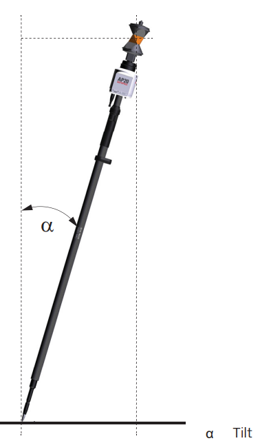
Tilt Compensation step-by-step
Tilt Compensation is only supported with sales variants AP20 T and AP20 when the controller is connected to a robotic total station via CCD18.
Tilt Compensation can be used if the controller is connected to a robotic TPS instrument.
- In any app, exceptions see below:
Open the Controller/Target container from the status bar. - Tap Prism Type.
- Select AutoPole
- To turn Tilt Compensation ON or OFF:
Tap on the Controller/Target container and select Tilt.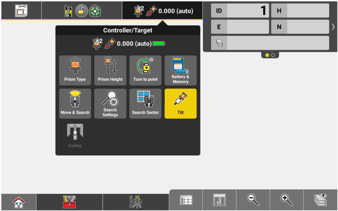
- Tilt Compensation is supported in the following Setup apps:
- Coordinates Anywhere
- Coordinates Over known point
- Control Line Anywhere
- Control Line As Built Walls
- Heights Transfer height anywhere
See also: General Description
- Tilt Compensation is not supported within the Sets of Angles and 2-Face app.
- Ceiling becomes available for selection when Tilt Compensation is ON.
Tap on the Controller/Target container and select in order to automatically measure the point on the ceiling, no matter how the pole is tilted.
- Tilt Compensation is supported in the following Setup apps:
- Tap Start in the measure bar.
- Move the pole for initialisation. Walking to the layout point is sufficient. The Start button changes to a green Store to indicate that the tilt compensation is being applied.

- The Tilt LED on the AP20 and the symbol for the pole in the status bar indicate when a tilt compensated measurement is possible. Refer to Description of the AP20 ON/OFF button and status LEDs.
- The tilt status indicator below the symbol for the pole in the status bar indicates the stability of the initialisation status. A nearly empty bar serves as a warning that tilt compensation may be lost if the device is not moved.

- Measure or stake a point.
- Once initialised, you can switch between applications without the necessity to re-initialise the AP20.
TargetID
TargetID provides an automatic target search and identification on-the-fly.
The common search methods, such as PowerSearch, are extended with an additional verification of an ID which is transmitted from the AP20.
While the total station is performing a search, it ignores any other target or foreign reflections and only stops and locks onto the target above the AP20.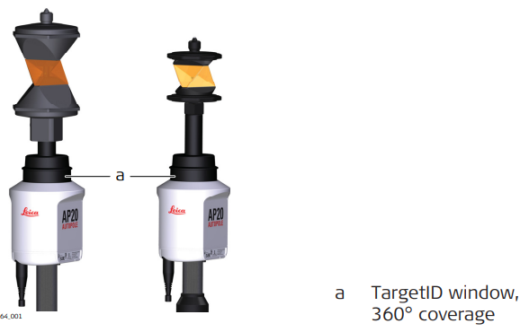
TargetID step-by-step
TargetID is only supported with sales variants AP20 ID and AP20.
TargetID can be used if the controller is connected to a robotic TPS instrument.
- In any app:
Open the Controller/Target container from the status bar. - Tap Prism Type.
- To turn the TargetID ON:
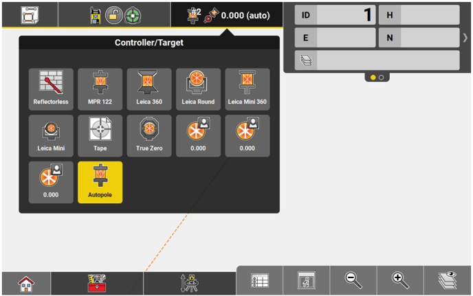
Select AutoPole as prism type from the status bar.
To turn the TargetID OFF: Select any pre-defined or user defined prism, except AutoPole.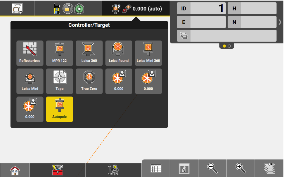
- Start a prism search.
