iCON site + iCON build Plus

| Function | Description |
|
Stake Elevation |
Stake out with reference to a height, which is defined: Cut/Fill values in the Information bar are altered according to the reference height applied. Side View is a kind of cross-section view and TPS only: If a Project Height Shift has been |
|
Reference Height
|
Stake out elements (points, lines, arcs) with reference to a height, which is defined: Cut/Fill values in the Information bar are altered according to the reference height applied. Refer to Stake Out Points, Lines, Arcs with Reference to a Height . |
|
Reference
|
Stake elements with reference to a line. |
| Function | Description |
|
New Point
|
Insert a point into the map by entering the required coordinates or by scanning a QR-code. This point can then be staked. The new point can also be defined as Control Point. ➜ To start the QR-code scan tap |
|
Edit Point
|
After selecting a point from the map, permitted values can be edited. |
|
Stake Writer
|
Enable this option to get guidance on marking of the stake. For further details refer to: Stake Writer |
|
Undo
|
Undo previous action. |
|
Delete
|
Remove points/lines/arcs. |

 is displayed in the Status Bar, when a Project Height Shift is applied to a project.

 .See also: Importing data using QR Scan step-by-step


| Function | Description |
|
Shift Point
|
Creates a new point shifted from the initially selected point by the entered offset values. |
|
Create Point /Line
|
Allows you to create a point or line by defining direction and slope. |
|
Auto Element Selection
|
Set this option to On to make the next point/ line to stake be selected automatically according to the settings. • Next Point from list: the next point from the Stakeout Point List is selected automatically. ➜ To use the Next Point from list or the Nearest Point from list function, it is necessary to define the list of points first. |
|
Auto Snap
|
Enable this option to make temporary points be displayed for dedicated points of elements to be laid out. For further details refer to: Stake out/Lay out points using Auto Snap |
|
Auto Staking
|
Lay out points automatically. See also: Layout a point on ceiling, floor or wall |
|
Stakeout List
|
Tap this button in order to add points via graphical selection to a Stakeout List. To be able to see the list next to the Map view switch on the Stakeout Point List from within the Map Handler > Viewing options |


Layout Lines Toolbox functions
iCON build + iCON site Plus
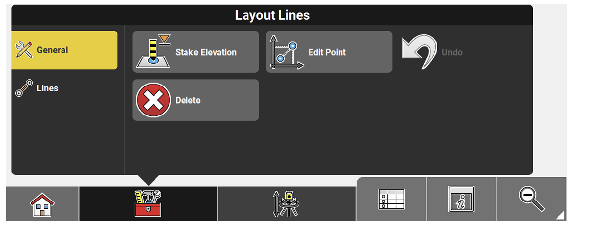
| Function | Description |
|
Stake Elevation
|
Set out with reference to a height, which is Cut/Fill values in the Information bar are altered according to the reference height applied. Side View is a kind of cross section view and only available when using Stake Elevation. When using a Robotic Total Station, a defined height can be set out automatically by tapping the Auto Staking button in the Measure bar. Height and autostake function stay active so that the same height can be autostaked on different walls. See also: Lay out a point on ceiling, floor or wall. |
|
Flip
|
Switch the start point and end point of the active line. |
|
Edit Point
|
After selecting a point from the map, permitted values can be edited. |
|
Undo
|
Undo previous action. |
|
Delete
|
Remove points/lines/arcs. |


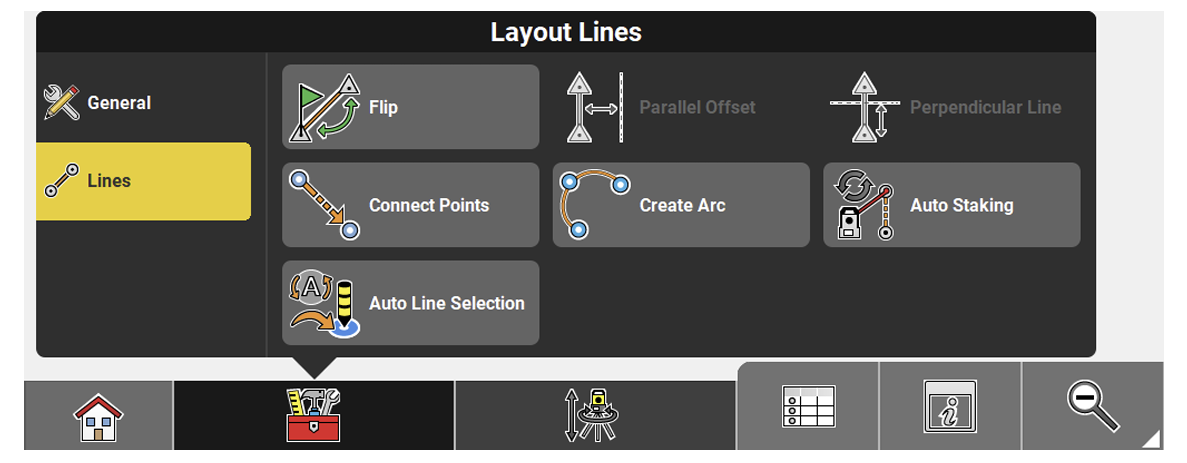
| Function | Description |
|
Flip
|
Switch the start point and end point of the active line. |
|
Parallel Offset
|
Offset a line to be set out. When an offset is applied, the Offset indicator is displayed in the top left corner of the map view. The indicator disappears when all possible offset values are set to zero. You can tap the Offset indicator to quickly access the toolbar. |
|
Perpendicular Line
|
Create a perpendicular line to be set out. When an offset is applied, the Offset indicator is displayed in the top left corner of the map view. The indicator disappears when all possible offset values are set to zero. You can tap the Offset indicator to quickly access the toolbar. |
|
Connect Points
|
Tap points to create a line to be set out. |
|
Create Arc
|
Tap points to create an arc to be set out. |
|
Auto Staking
|
When a line (pipe) is be selected, the break through point can be laid out automatically on the wall. See also: Lay out a point on ceiling, floor or wall |
|
Auto Line Selection
|
Set this option to On to make the next line to stake be selected automatically by the instrument according to the settings: ➜ Calculation of the nearest line is based on 3D coordinates. |


