Jump To:
General InformationPreparation
Combined adjustment procedure step-by-step
Calibration report
General Information
Leica Geosystems instruments are manufactured, assembled and adjusted to
the best possible quality. During the manufacturing process, the instrument
errors are carefully determined and set to zero. When the instrument is in use,
though, and exposed to external influences, errors can increase and it is highly
recommended to redetermine them in the following situations:
- Before the first use
- Before every high precision survey
- After rough or long transportation
- After long working periods
- After long storage periods
- If the temperature difference between current environment and the temperature at the last calibration is more than 68°F or 20 °C
Quick temperature changes, shock or stress can cause deviations and decrease the instrument accuracy.
ATR acTo get precise measurements in daily work, it is thus important:
- To check and adjust the instrument from time to time.
- To take high precision measurements during the check and adjust procedures.
- To measure targets in two faces. Some of the instrument errors are eliminated by averaging the angles from both faces.
Check and adjust can be done in the field by running through specific measurement procedures. The procedures are guided and must be followed carefully and precisely as described in the following chapters. Some other instrument errors and mechanical parts can be adjusted mechanically.
Mechanical adjustment
The following instrument parts can be adjusted mechanically:
- Circular level on instrument and tribrach
- Optical plummet - option on tribrach
- Allen screws on tripod
Electronic adjustment
The following instrument errors can be checked and adjusted electronically:
| l, t | Compensator longitudinal and transversal index errors |
| i | Vertical index error, related to the standing axis |
| c | Horizontal collimation error, also called line of sight error |
| a | Tilting axis error |
| ATR | ATR zero point error for Hz and V - option |
☞ If the compensator and the horizontal corrections are activated in the instrument configuration, every angle measured in the daily work is corrected automatically.
Impact of errors that can be adjusted electronically
| Instrument error | Effects Hz | Effects V | Elimination with two face measurement | Automatically corrected with proper adjustment |
| c - Line of sight error | ✓ | − | ✓ | ✓ |
| a - Tilting axis error | ✓ | − | ✓ | ✓ |
| l - Compensator index error | − | ✓ | ✓ | ✓ |
| t - Compensator index error | ✓ | ✓ | ✓ | |
| i - Vertical index error | − | ✓ | ✓ | ✓ |
| ATR Collimation error | ✓ | ✓ | − | ✓ |
Preparation
- Before determining the instrument errors, the instrument has to be levelled using the electronic level. The tribrach, the tripod and the underground should be stable and secure from vibrations or other disturbances.
- The instrument should be protected from direct sunlight to avoid thermal warming. It is also recommended to avoid strong heat shimmer and air turbulence. The best conditions are early in the morning or with overcast sky.
- Before starting to work, the instrument has to become acclimatised to the ambient temperature. Take at least 15 minutes into account or approximately 2 minutes per °C of temperature difference from storage to working environment.
- Even after adjustment of the ATR, the crosshairs may not be positioned exactly on the centre of the prism after an ATR measurement has been completed. This outcome is a normal effect. To speed up the ATR measurement, the telescope is normally not positioned exactly on the centre of the prism. These small deviations/ATR offsets, are calculated individually for each measurement and corrected electronically. This means that the horizontal and vertical angles are corrected twice: first by the determined ATR errors for Hz and V, and then by the individual small deviations of the current aiming.
Combined adjustment procedure step-by-step
The combined adjustment procedure determines the following instrument errors in one process:
| l, t | Compensator longitudinal and transversal index errors |
| i | Vertical index error, related to the standing axis |
| c | Horizontal collimation error, also called line of sight error |
| ATR Hz | ATR zero point error for horizontal angle option |
| ATR V | ATR zero point error for vertical angle option |
The following description explains the most common settings:
☞ It is recommended to use a clean Leica circular prism as target. Do not use a 360° prism.
- For ATR calibration connect the device with the Instrument.
- Go to Settings > Devices from within the Home screen.

- Select your instrument and tap the arrow.
- When using iCON build the device settings are available from within Status Bar 1.
- When being connected to an iCON iCR50, iCON iCR70 or iCON iCR80S or to an iCON iCT30 via the controller, or when using the onboard software of any iCON driven TPS, the TPS calibration report function is available.
For information on the calibration report, refer to Calibration report .
The calibration report can also be exported. Refer to Exporting data step-by-step.
- Go to Settings > Devices from within the Home screen.
- Select Sensor Calibration.
- Select the incl. ATR Calibration option if you like to calibrate the ATR. For ATR callibration a Leica round prism is needed. For Angle callibration no prism is required.
- If applicable, tap Report to view a list of all calibration reports. Tap the name of a report to show the respective calibration results. If no calibration reports are available yet, the button is greyed out.
- To start calibration, tap
 . Follow the wizard which guides through the calibration.
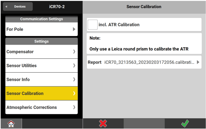
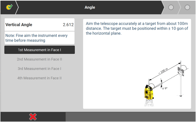
- Aim the telescope accurately at a target at about 100 m distance. The target must be positioned within ± 9°/± 10 gon of the horizontal plane. Start the procedure in telescope face one.
- Press the measurement keys to measure and to continue to the next step.
- Motorised instruments change automatically to face one after tapping on the next measurement.
- For ATR calibration the target must be a Leica round prism.
- The fine pointing has to be performed manually in both faces.
- Tap
 in the wizard to get to the next page.
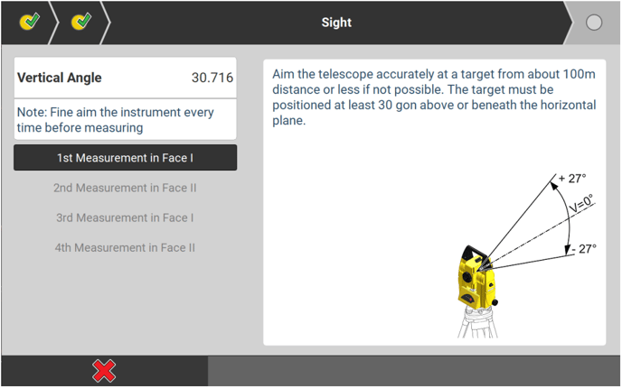
- Aim the telescope accurately at a target at about 100 m distant or less if not possible. The target must be positioned at least 27°/30 gon above or beneath the horizontal plane.
- Press the measurement keys to measure and to continue to the next step.
- Motorised instruments change automatically to the other face.
- The fine pointing has to be performed manually in both faces.
- Adjustment Accuracy
After pressing the last in the wizard, the results are shown and stored to the instrument.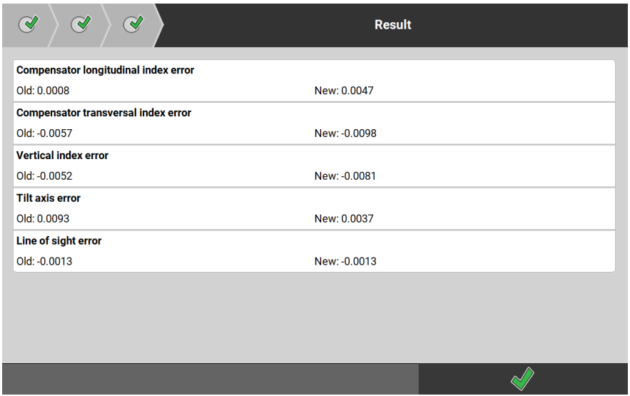
- Tap to get back to the Devices page.
Calibration report
The purpose of the calibration report is a documentation of the results of the field calibration. The report proofs the quality of the equipment for quality insurance.
At the end of the sensor calibration, a report (*.calibration) is created automatically. The report contains all calibration values.
The report is stored on the hard drive of the controller (for instruments with keyboard unit only):
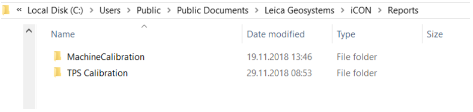
The reports and results of past calibrations can also be exported. Select Export from the Home screen/Admin Panel. Tap within the section Details and select TPS Calibration.