Overview
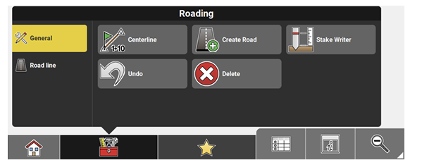
| Function | Description |
|
Centerline
|
Allows the user to change the centreline of the road model. The result is a new XML road model based on the new centreline. You can switch between both road models by selecting one or the other *.xml file via the Map View Manager. |
|
Create Road
|
Convert exisiting reference data into a roading file. Resulting file format: *.xml Refer to Convert reference data into a roading file step-by-step. |
|
Stake Writer
|
Enable this option to get guidance on marking of the stake. For further details refer to: Stake Writer |
|
Undo
|
Undo previous action. |
|
Delete
|
Remove points/lines. |


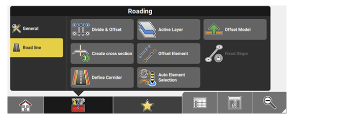
| Function | Description |
|
Divide & Offset
|
Divide a line or arc into segments. When using this function the Offset feature is available as well. Therefore a line or arc can be divided into segments and the segment points be offset in one step. Refer to Use Divide & Offset step-by-step . |
|
Active Layer
|
Select the active layer of the current active road line model. |
|
Offset Model
|
Offsets the whole model by entered value. When an offset is applied, the Offset indicator is displayed in the top left corner of the map view. The indicator disappears when all possible offset values are set to zero. You can tap the Offset indicator to quickly access the toolbar. |
|
Create cross section
|
Create cross-sections using different methods. |
|
Offset Element
|
Offsets the selected element, for example cross When an offset is applied, the Offset indicator is displayed in the top left corner of the map view. The indicator disappears when all possible offset values are set to zero. You can tap the Offset indicator to quickly access the toolbar. |
|
Fixed Slope
|
Hold and extend the slope of a selected cross slope element. |
|
Define Corridor
|
Corridor function for cross-sections. Define the ➜ Cross-section calculation is restrained by the defined corridor. ➜ Useful for curvy roads. |
|
Auto Element Selection
|
Set this option to On to make the next point/ line to stake be selected automatically according to the settings. |
|
|
• Next Point from list: the next point from the Stakeout Point List is selected automatically. • Nearest Point (or line): the point or line in • Nearest Point from list: the point from the Stakeout Point List that is closest to the current position is selected automatically after the previous point was staked out. • Nearest Line in direction: only works for vehicle/dozer/scraper and tractor configurations. The line closest to the current position is selected automatically. Lines on the • Dynamic Point selection: the point closest to the current or last known pole/rover position is selected automatically. ➜ To use the Next Point from list or the Nearest Point from list function, it is necessary to define the list of points first. ➜ Calculation of the nearest point or line is based on 3D coordinates. ➜ Lines at a 3D distance larger than 10m are not selected automatically. ➜ Auto Element Selection can be activated separately for each Stakeout/Layout application and will stay active even after restart. The chosen method will stay selected in the Stakeout/Lay |