1.Introduction
2.Create a road from 3D polylines
3.Importing data
4.Different views
5.Road data
6.The functions in the toolbox
To use the Roading module, users must obtain the required license.
The license can be obtained from Article 793844 CSW 213, the iCON app “Roading.”
The Roading module is essential for road construction projects. It enables the importation of corridors, alignments, and the creation of corridors from 3D or 2D polylines with surface. The cross-section view and hold slope features make it easier to comprehend and utilize the data. The toolbox offers a range of functions that enhance versatility and efficiency during road contract execution.
Create a road from 3D polylines
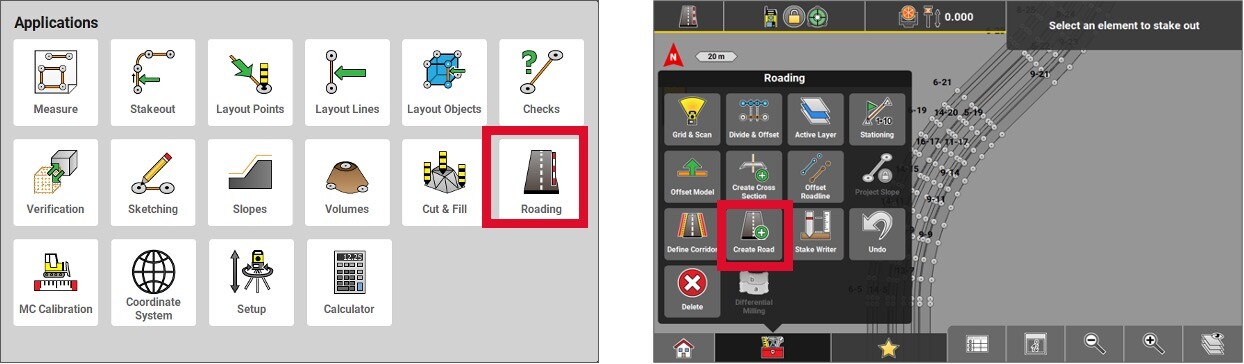
First, import the CAD file where the road polylines are located. Then, enter the Roading application.
In the Toolbox, press Create Road.
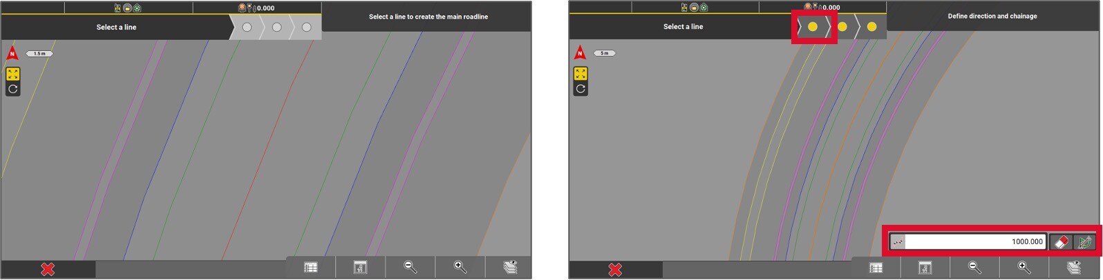
- Follow the steps indicated on the top left corner of the screen. Select the primary alignment (centerline).
- Enter the initial chainage (for instance, 1000.000). If necessary, you can swap the start and end points of the road. Press the yellow dot to proceed.
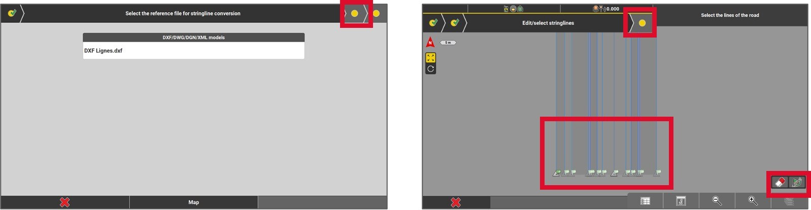
- Select the reference model to convert it into a « stringline » model. Once it is selected, press on the yellow dot to continue.
- All the other lines will be automatically selected as part of the road, although specific lines lines can be unselected. At this step, it is also possible to swap the start and the end points of the road if required. Click on the yellow dot to continue.
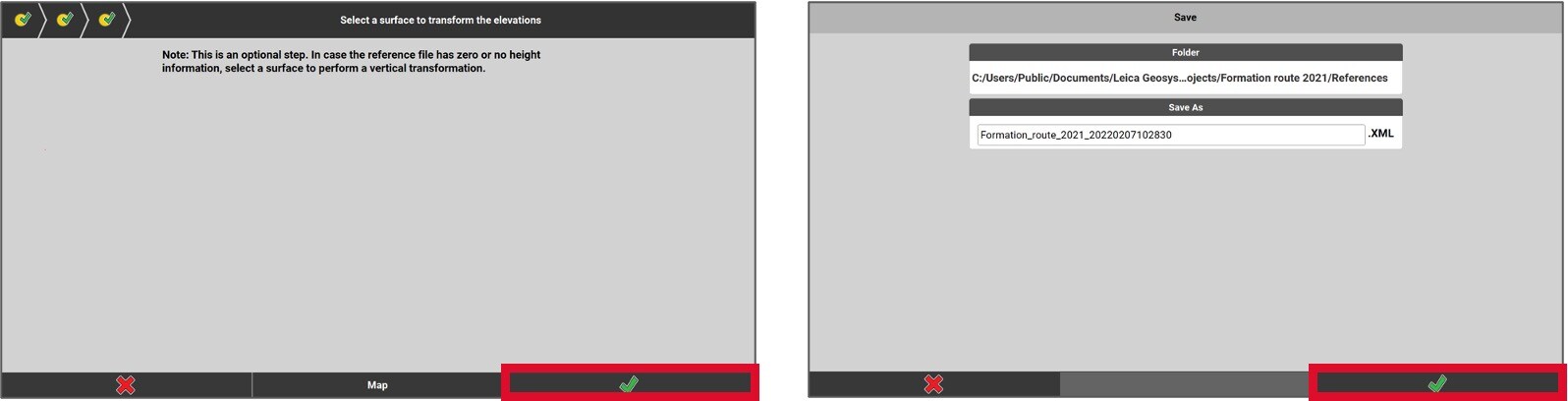
- At this point, if the file lacks elevation data, choose a surface model to vertically transfer the road lines. To accomplish this, press on the Map button and select the surface. If the file already includes accurate elevations, simply press the green checkmark.
- Next, name the document you’re about to create and then select the green checkmark.
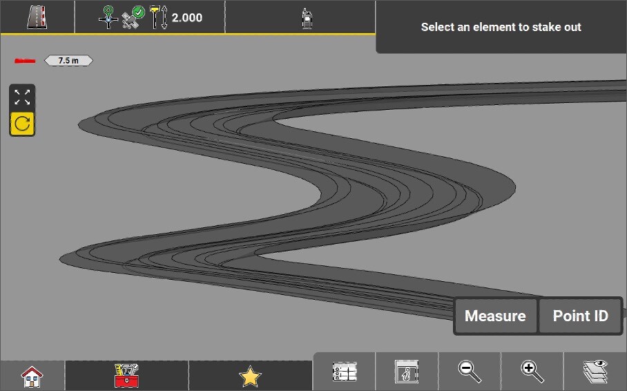
The road is now created, it is now possible to stake out elements by using the Roading application.
Importing an XML alignment or a road project
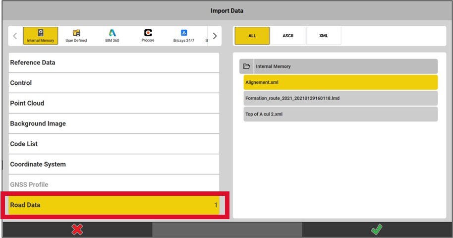
To import an XML road alignment or corridor, select the Road Data option. For importing an existing road project (LMD or XML), ensure that the Road Data type is also selected.
Roading applications views
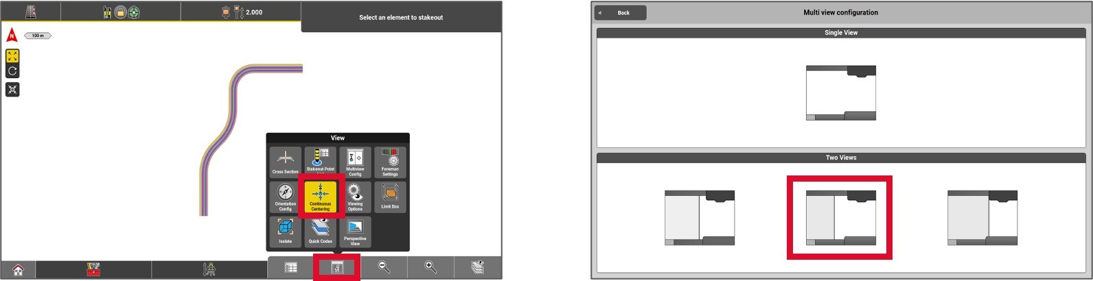
The screen can be divided into two, providing different perspectives of the project.
To divide the screen, click on the View settings button (i) and then select Multiview Config.
Choose the configuration that best suits your work screen.
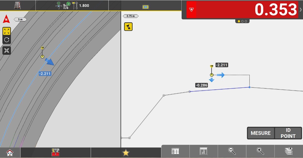
To obtain a cross-sectional view, select the desired window where the cross-sectional view will be displayed. Then, click on View (i) and select Cross-section.
Two positional perspectives will then be presented simultaneously: one in plan and one in section.
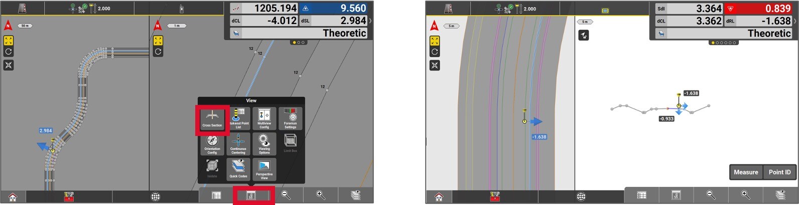
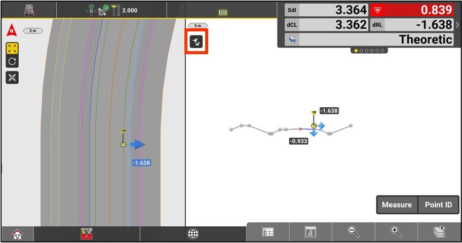
The cross-sectional view in the Roading application changes direction based on the user’s direction of travel. You can block a specific direction by pressing the button at the top left corner of the sectional view.
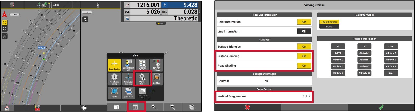
It is possible to setup different display parameters by choosing Viewing options in the View menu.
You have two options:
Turn the road shading ON / OFF.
Change the scale of the vertical exaggeration of the slopes in the Cross Section page.
Pictograms detail
In the Route application, data is available in the information bar. The following section shows data specific to this application.
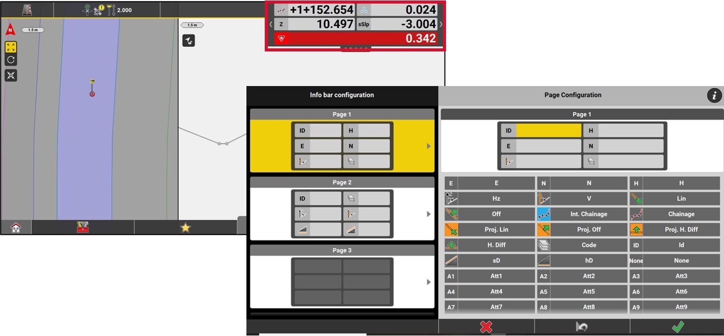
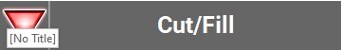
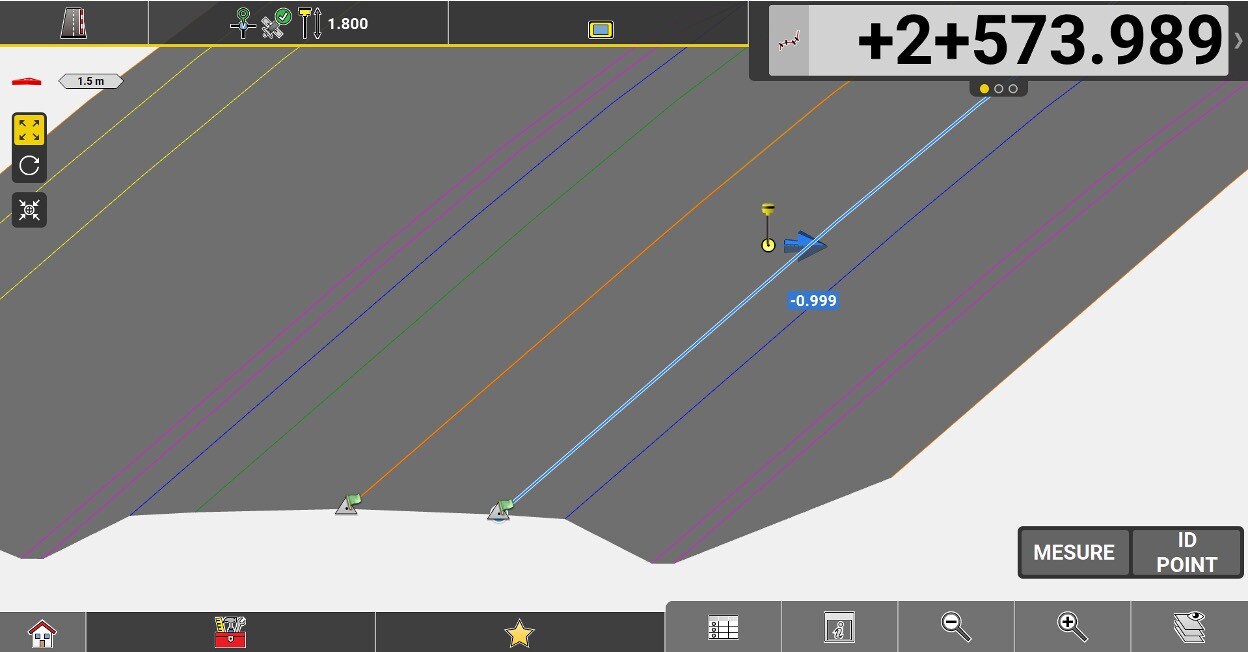
Value of cut/fill in relation to the height of the element being staked.
Chainage of the center line.
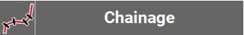
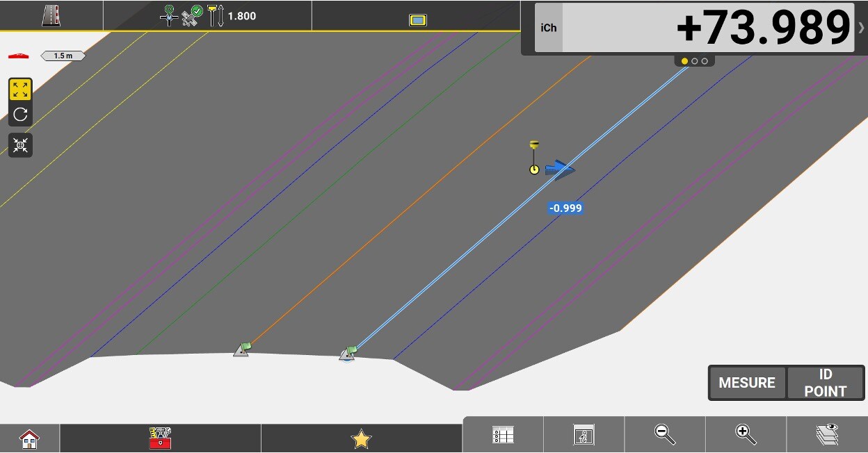
Chainage to the selected reference line without applying a start chainage.
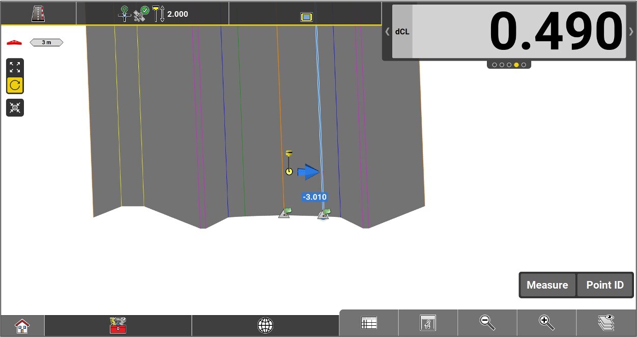
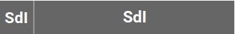
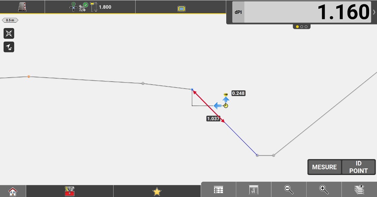
Perpendicular distance between the centerline and the measured position. A negative value means that the position is to the left of the line.
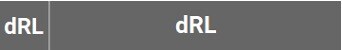
Perpendicular distance between the reference line and the measured position. A negative value means that the position is to the left of the line.
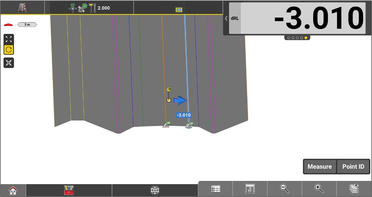
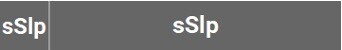
Slope of the cross section at the measured location. The value is negative if the slope goes down from the Centerline.

Important note: In stakeout, "sSlp" becomes the perpendicular slope connecting the measured position to the reference line. The value is negative if the position is above the line.
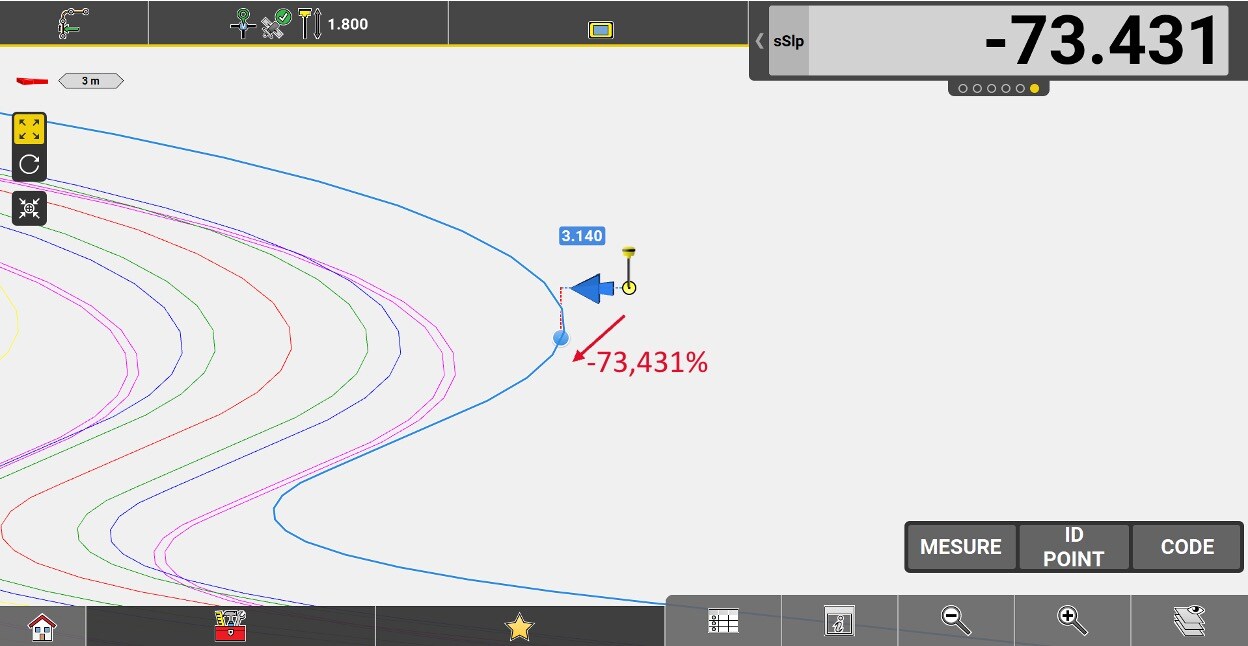
Longitudinal slope (along the line) of the selected line, at its closest point to the measured position.
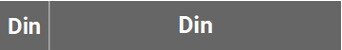
Distance from the measured position to the inner edge of the current element (the edge closest to the axis).
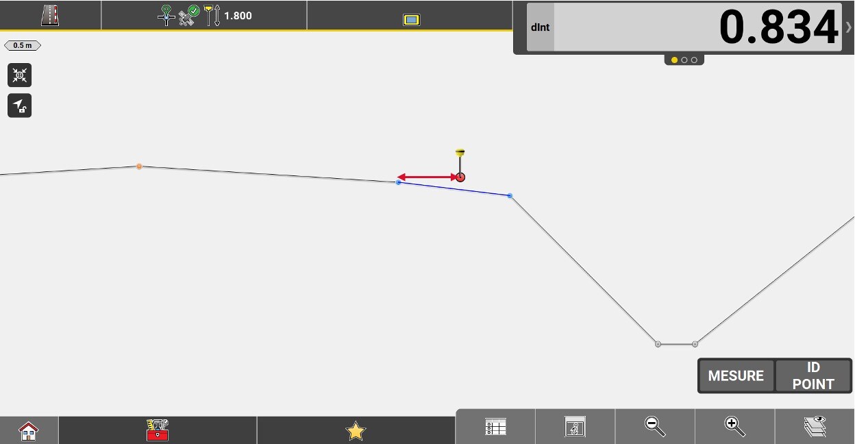
Distance from the measured position to the outer edge of the current element (the edge farthest from the axis).
Slope distance from the measured position to the inner edge of the current element (the edge closest to the axis).
Slope distance from the measured position to the outer edge of the current element (the edge farthest from the axis).
The horizontal distance from the measured position to the current chainage where the current height intersects the theoretical road profile.
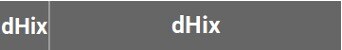
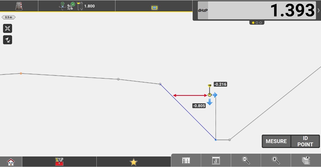
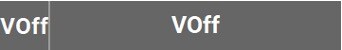
Height difference of the measured position from the selected reference line.
Vertical offset value applied to the road model.
Perpendicular height difference from the measured position to the slope.
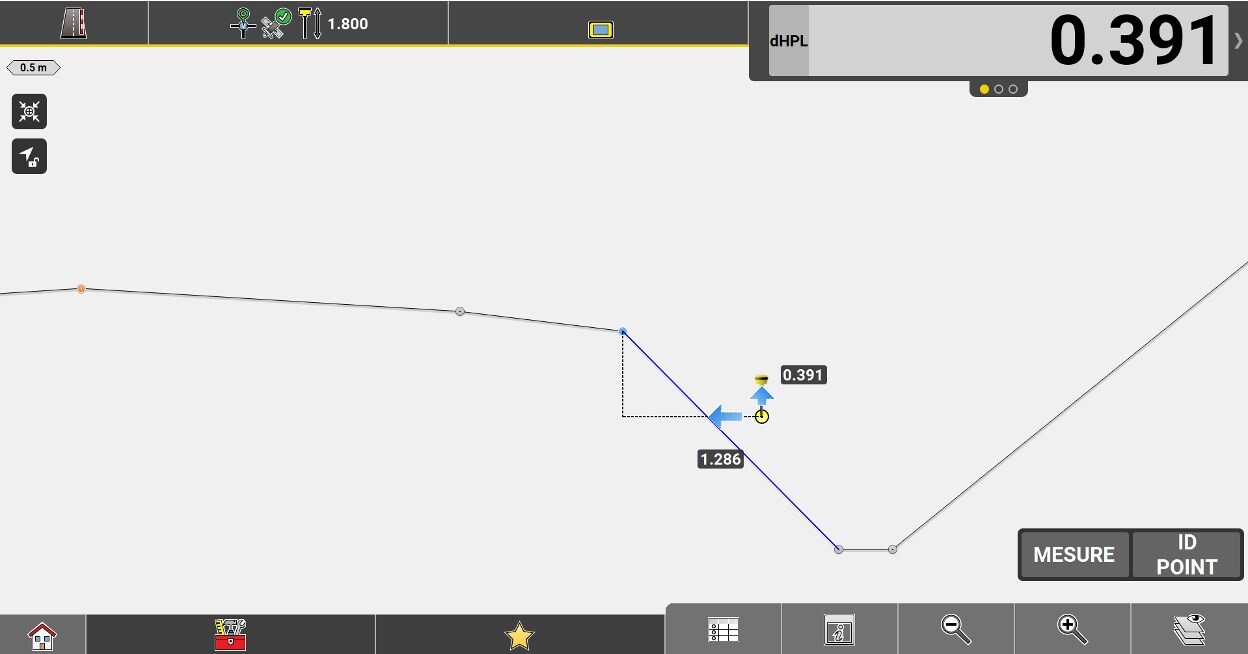
Vertical offset value applied to the implanted element.
Functions of the Roading application
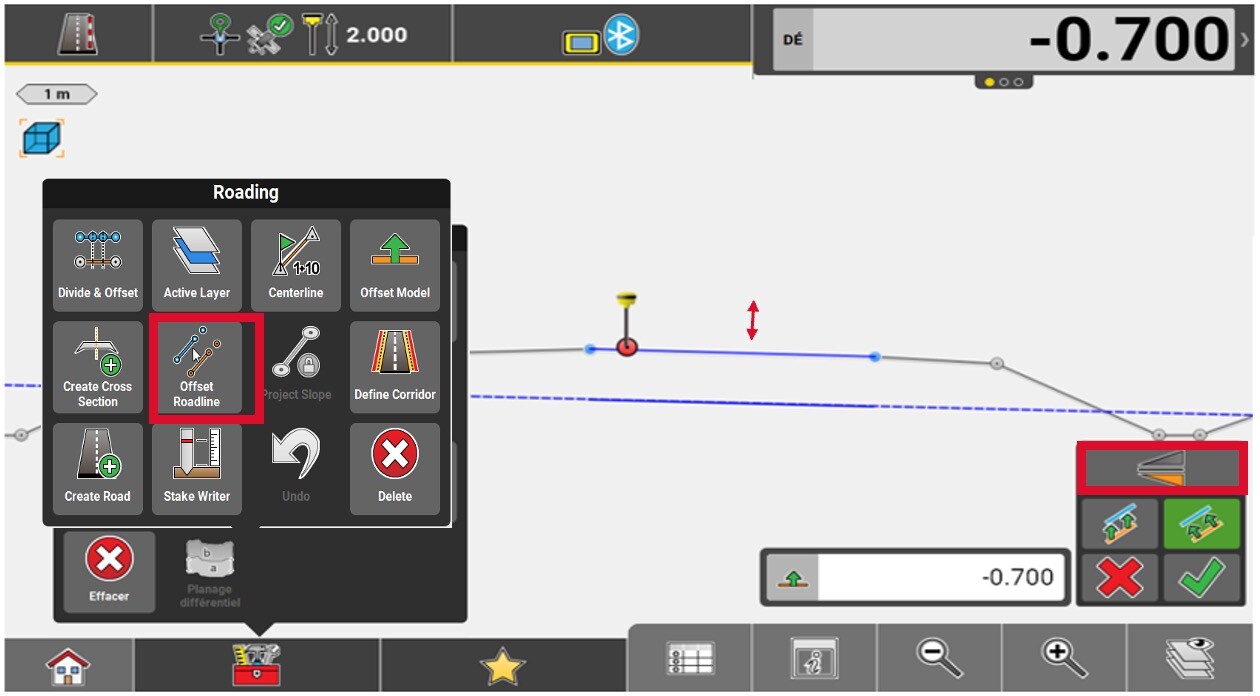
To split and offset a polyline into multiple points, go to the Toolbox and press Divide & Offset.
Select the polyline and use the options in the lower right corner of the map, to split and offset the polyline. A list of location points will be created.
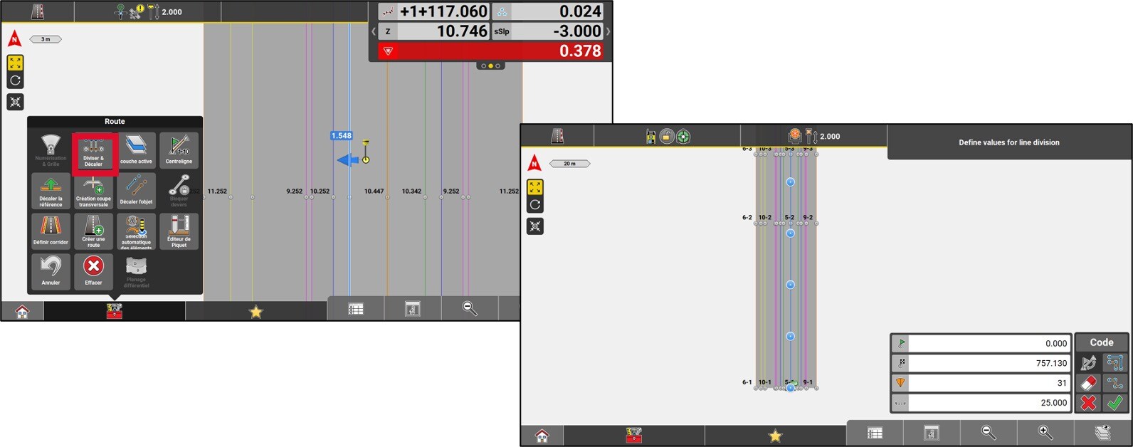
To change the active reference layer of the current road model, go to the Toolbox and press Active layer.
Select the desired layer.
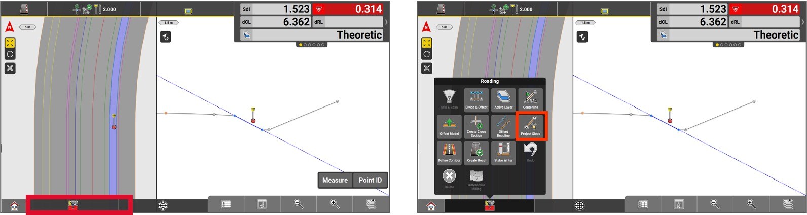
The slope is now elongated and can now be used as required by the user.
To unlock the slope, access the toolbox menu and select Variable slope.
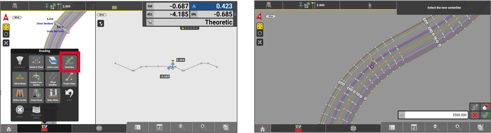
In order to change the center line and/or, change the starting chainage of an alignment or a polyline, access the Tool box and select Centerline.
Select the desired centerline and enter the start chainage to apply it to the element. Press the Green checkmark. This function generates a new road file in XML format. The previously created file will be disabled.
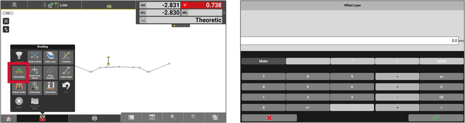
The entire lenght of the road model can be offset. To do so, access the Toolbox and select Offset model .
Enter the offset value by pressing on the Green checkmark. This offset reflect on the vertical scale.
The entire lenght of the road model can be offset. To do so, access the Toolbox and select Offset model .
Enter the offset value by pressing on the Green checkmark. This offset reflect on the vertical scale.
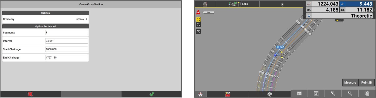
To create stakeout points of profile sections, access the Toolbox and select Create a cross-section.
Determine if the points need to be linked to a specific chainage or regular interval. In this example the chainage option is selected.
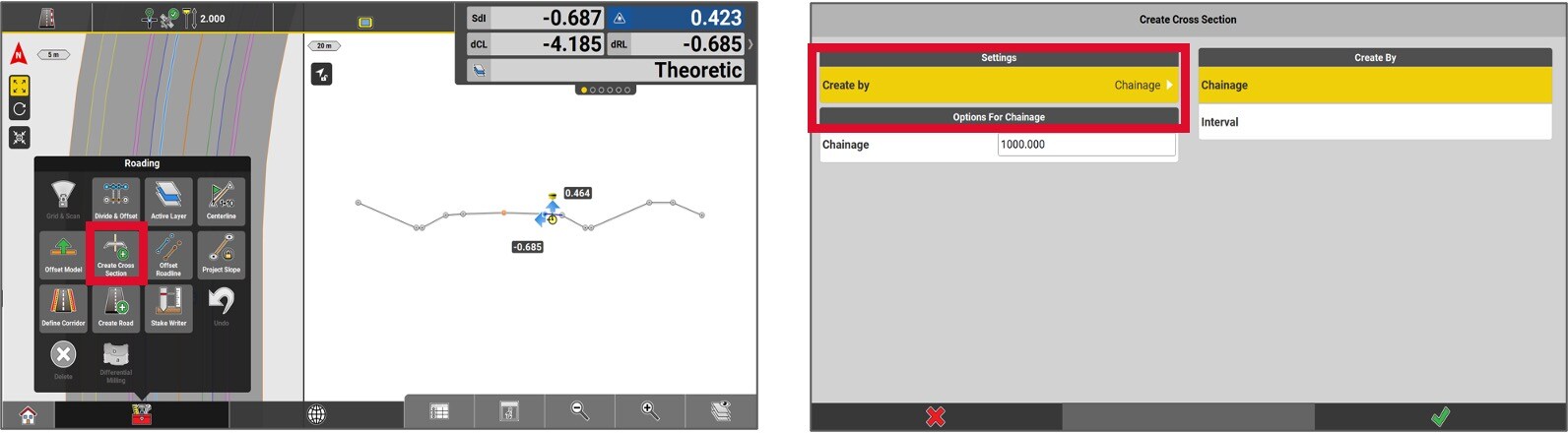
If the regular interval option is more convenient to the user, select interval. Fill the required fields to the point creation and hit the green checkmark.
The points will be created, and it will then be possible to stake them out.
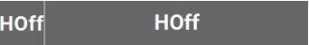
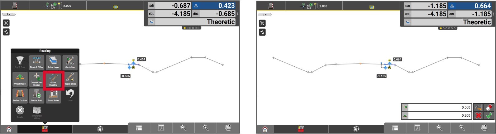
To offset an element, we start by selecting it. Then, access the Toolbox and select Offset Roadline.
Enter the offset value and then press the Green checkmark.
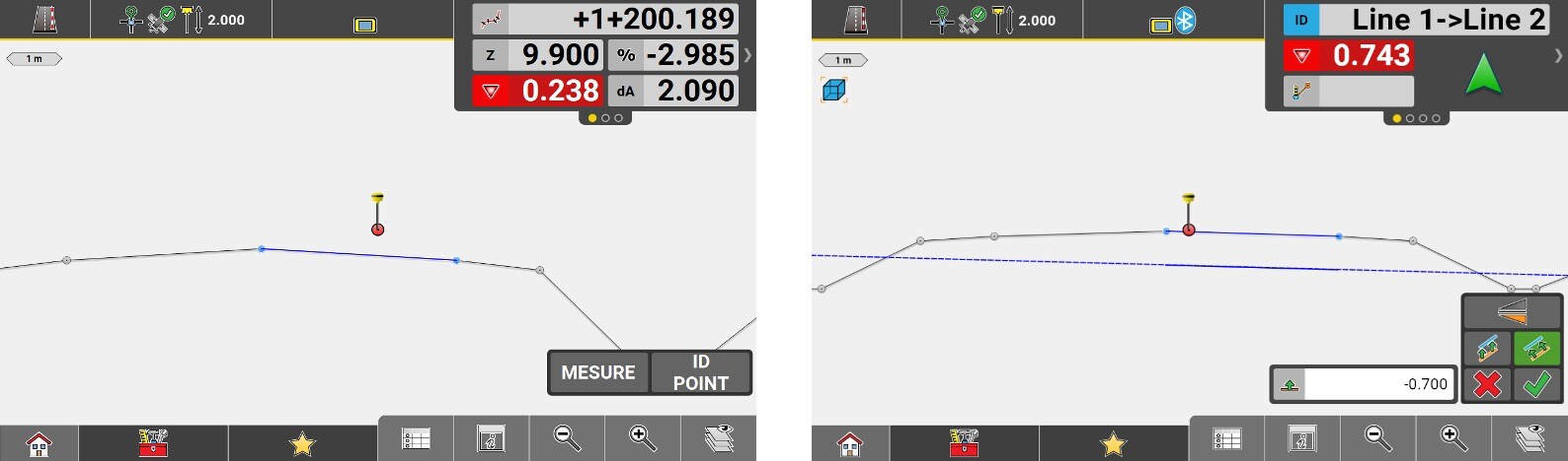
It’s also possible to shift a slope. Select the slope, then press Shift Object.
Enter the offset value and ensure that you offset in the desired direction, either vertically or perpendicular.
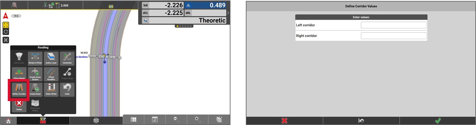
To define the road right-of-way, go to the Toolbox and select Define Corridor.
Enter the values that will define the road right-of-way on either side of the centerline.