Logging points with Leica MC1 machine control software offers significant benefits for construction projects by enhancing accuracy, efficiency, and collaboration. The software enables operators to collect precise as-built data directly from the machine's position, eliminating the need for separate survey crews. By integrating with GNSS or total station systems, Leica MC1 provides real-time georeferenced updates, ensuring the logged points align accurately with the project design. This streamlined process reduces downtime and allows machines to operate continuously, enhancing workflow efficiency and minimizing survey costs.
Moreover, regular point logging improves quality control by creating a detailed record of progress, which helps supervisors monitor and verify the work against design specifications. The data can be easily exported and shared with stakeholders, simplifying collaboration and ensuring everyone works with consistent information. Leica MC1’s seamless integration with cloud platforms like ConX further supports real-time data sharing and documentation. These capabilities not only ensure compliance with project requirements and regulatory standards but also provide valuable records for client handovers or dispute resolution. Whether used in earthworks, utilities installation, or road construction, logging points with Leica MC1 ensures precision, simplifies complex design execution, and delivers a higher level of confidence in project outcomes.
Logging Points in Leica MC1 Using the As-Built Application
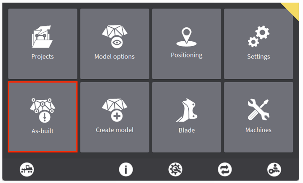
Step 1: Accessing the As-Built Application
From the Home Screen in Leica MC1, select the “As-Built” application.
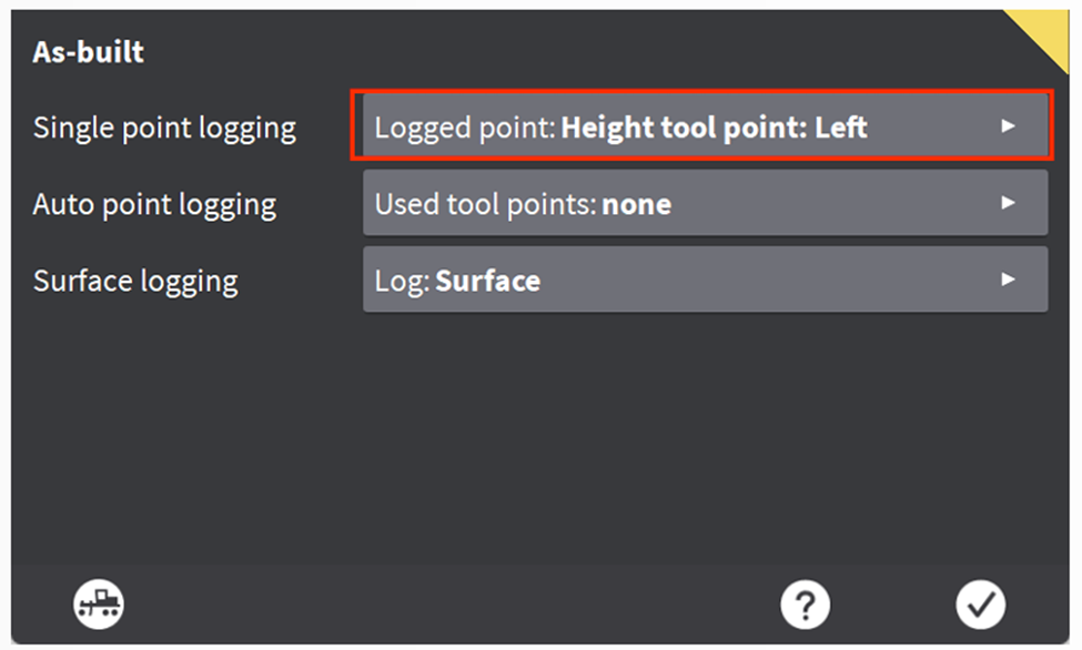
Step 2: Configuring Logging Options
Select Single Point logging to access the configuration menu.
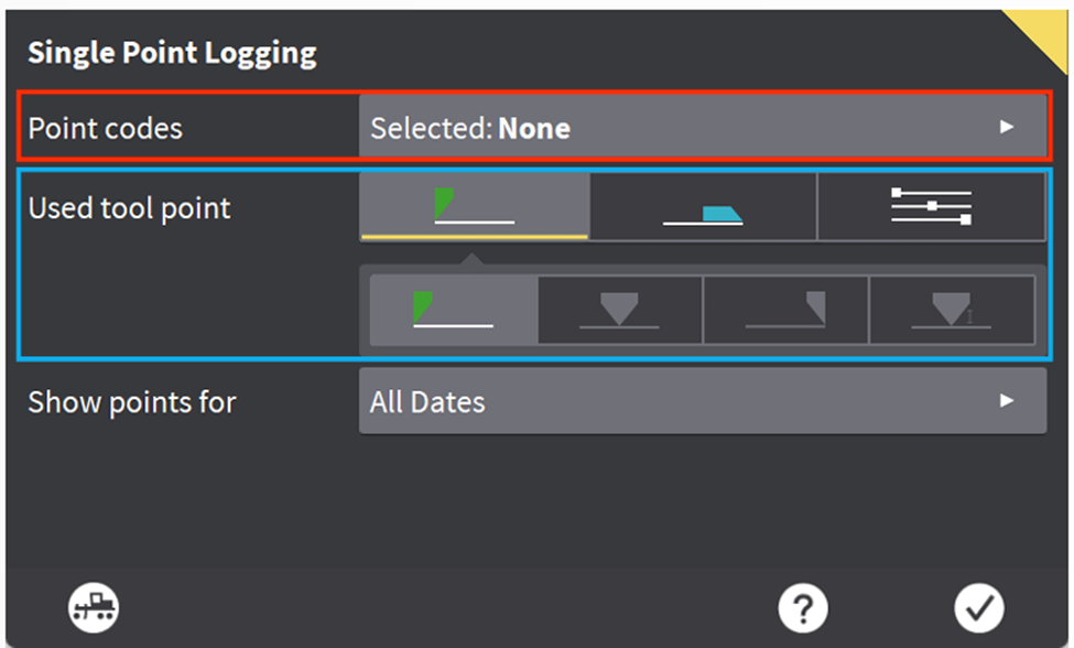
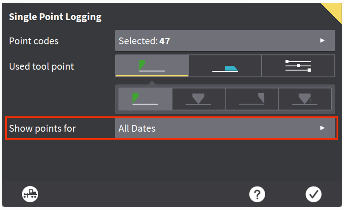
The Single Point Logging screen offers various configuration options for logging points:
- Point Codes: Use this feature to add descriptions to each logged point, enhancing clarity and organization.
- Used Tool Point: This setting determines where on the bucket or blade the point will be recorded.
- Green Icon (Height Reference): Points are logged based on the current height reference on the bucket.
- Blue Icon (Side Reference): Points are logged based on the current side reference on the bucket.
- White Icon (Manual Selection): Allows manual selection of positions along the bucket or blade for point logging, independent of height or side references.
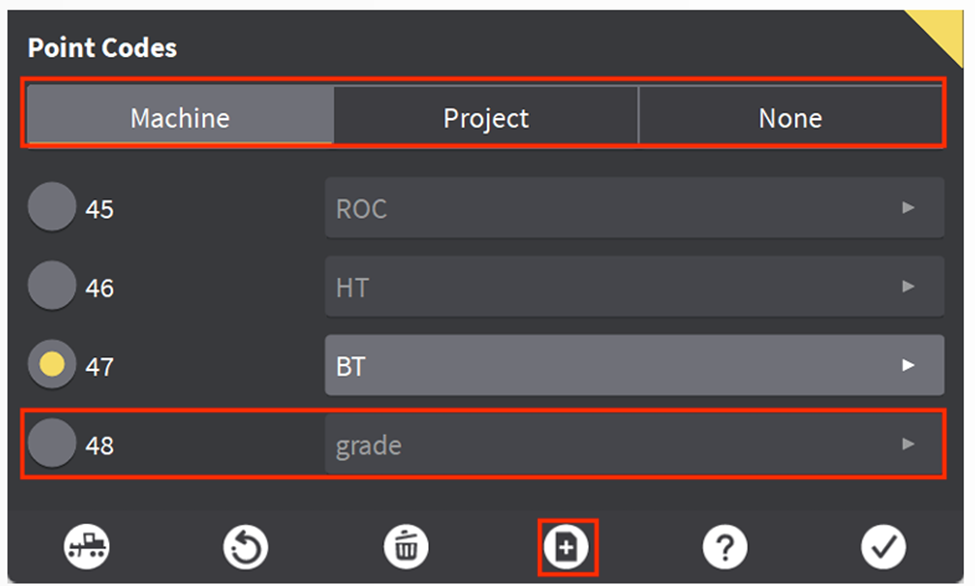
Step 3: Configuring Point Codes
To create or manage Point Codes:
- Select the Point Code button.
- To manually add a new Point Code, click the folder with the plus icon.
- To use a pre-defined Point Code list, select the “Project” tab. Importing a code list into the project can save significant time and improve workflow efficiency.
Once the Point Codes are configured, confirm your settings by selecting the check mark. This will return you to the Single Point Logging Menu.
Step 4: Setting Display Options
The final option on the Single Point Logging screen allows you to choose whether to display points logged during the current workday or for the entire project.
Step 5: Logging a Point
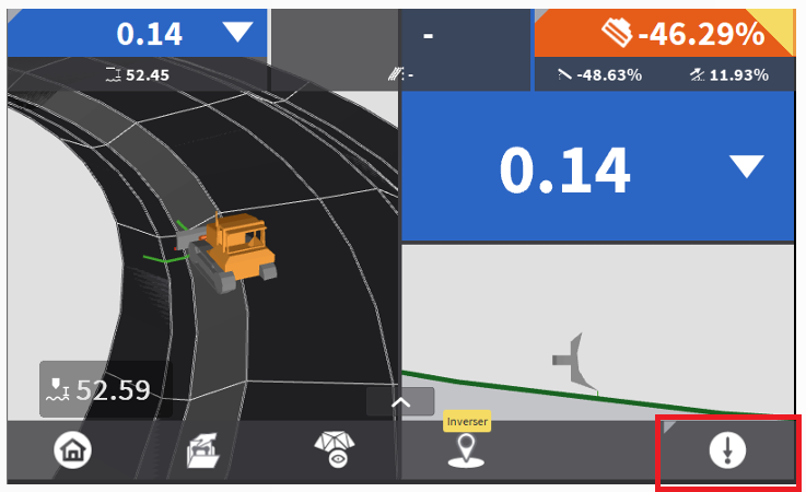
Return to the Run Screen by selecting the Dig/Grade button in the bottom left corner. To manually log a point, select the Log Point button in the bottom right. The point will be logged at the specified location based on your configurations.
Additional Features and Notes
-
Adjust Settings on the Fly:
Tap and hold the Log Point button to access a menu where you can change settings, such as selecting different codes.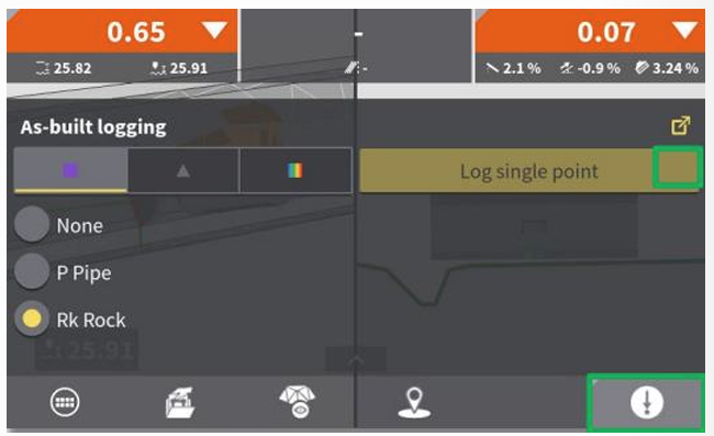 Use the Expand Button in the top right of this menu to quickly return to the Single Point Logging Menu to adjust code lists or the point location along the bucket/blade.
 -
Point Logging Details:
When a point is logged, a Revert option is available for a few seconds, allowing the operator to remove the point if necessary. If not reverted, the point is permanently stored in the file.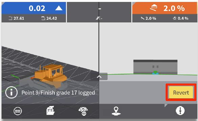 Previously logged points are displayed as purple squares on the map, depending on the configuration.
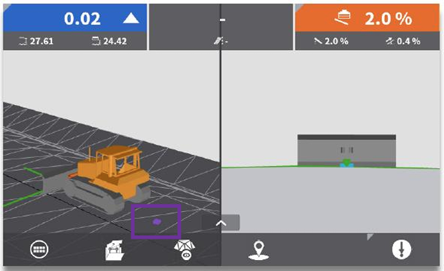
-
Multi-Machine Collaboration in ConX:
If multiple machines are connected to the same ConX project, logged points from other machines will also be visible. -
Exporting Points from ConX:
Points logged within a ConX project cannot be exported via USB. They must be extracted through the FilesAsbuilt tab in ConX. -
Survey Point File Data Structure:
The exported.csvfile contains detailed information, including:- Point number, code, and description
- Coordinates (East, North, Altitude, Latitude/Longitude WGS84, and Ellipsoidal height)
- GNSS accuracy (CQ3D), date, and time
- Machine name in ConX, panel serial number, and bucket name
- Reference details (height, height offset, and transversal reference information)
- Distance to reference points, chaining, and centerline distance
-
Survey Point File Creation and Export:
A survey point file is automatically created using the name of the active reference. Files can be exported via USB or accessed directly in ConX.- File names follow this structure:
- Active reference name.extension.csv (e.g.,
HighwayE20.xml.csv) - When synchronized with a USB, the MCP80 display's serial number is appended to the file name (e.g.,
HighwayE20.xml.123456.csv). - Files are stored in the Asbuilt subfolder under the project directory on the USB (e.g.,
USB/Projects/Leica Highway/Asbuilt).
- Active reference name.extension.csv (e.g.,
- File names follow this structure: