Jump To
Tap & Hold Functionality
Status bar ![]()
Status bar ![]()
Status bar for internal GNSS ![]()
Warning bar
Information bar
Main map area
Map handler
Measure bar
Function bar
Wizards
Virtual Keyboard
Tap & Hold Functionality
Some buttons/items in the iCON software offer additional functionality when you tap & hold the button/item.
Advanced functionality that becomes available by tap & hold is available on:
|
The Info panel in order to access the Info bar configuration screen See also: Information bar |
 |
|
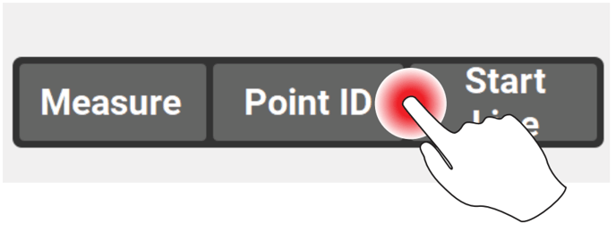
The Measure bar in order to access the Measure bar configuration screen See also: Measure bar |
 |
|
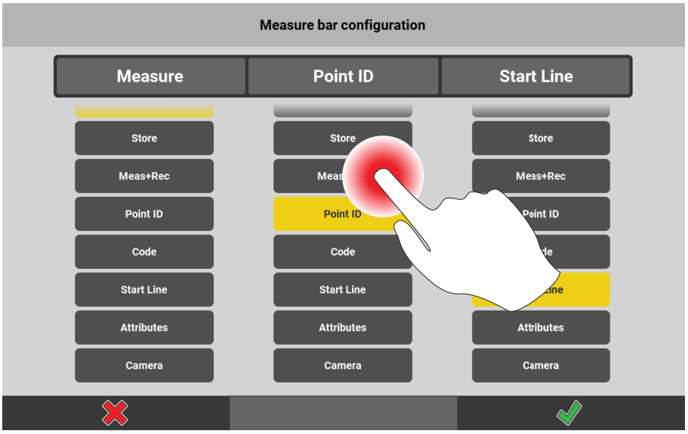
Any button in the Measure bar configuration screen in order to add its function to the Favourites key. See also: Measure bar |
 |
|
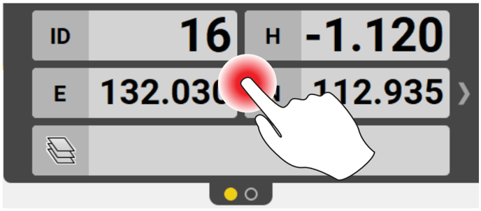
Any point symbol in the Map View in order to access the Point Information screen See also: Display point information |
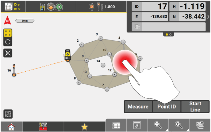 |
|
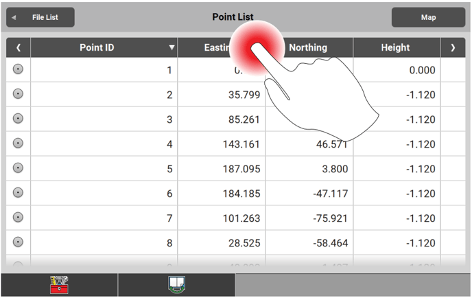
Any of the column headers in the Point List in order to access the Point List Configuration screen. See also: How to use Point List step-by-step |
 |
| Any point in the Point List in order to access the Point Information screen | 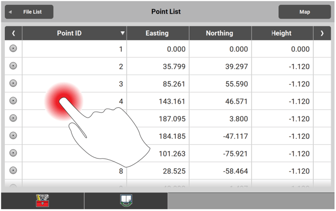 |
| Any project or job thumbnail in order to edit the project ot job properties | 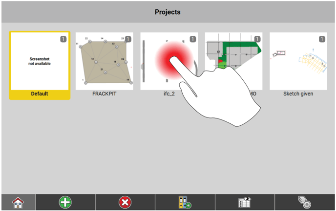 |
For the following buttons a little arrow in the bottom right corner indicates that additional functionality is available:
|
Zoom in/Zoom out Tap & hold to enable Smart Zoom See also: |
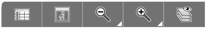 |
|
User-defined Prism Type/Hidden Point
See also: |
 |
|
User-defined Prism Height Tap & hold to define a prism height See also: |
 |
|
User-defined source/destination in Import/Export Tap & hold to define a source/destination path for data import/export See also: |
sta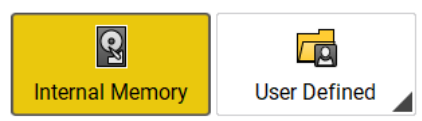 |
|
Functions manually added to Favourites Tap & hold to remove functions from the Favourites key that have manually added to the Favourites key from the Measure bar See also: |
 |
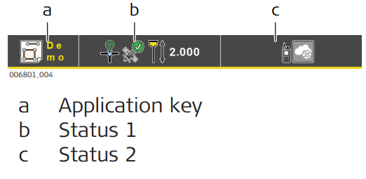
Status bar 
Status bar displays the status of the controller, the status of the connected instrument, pole and prism information, and information about the current application. It consists of three keys:
iCON site / iCON site Plus
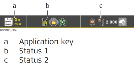
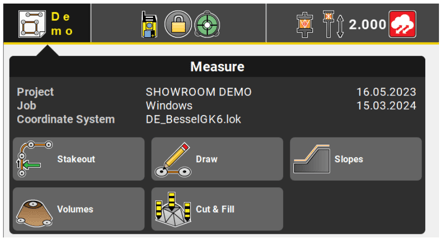
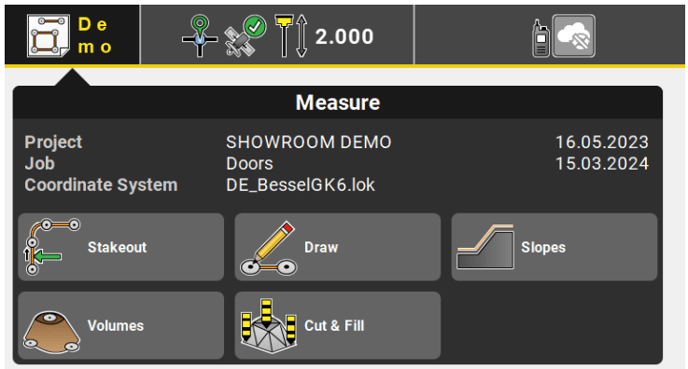
a Application key
iCON site / iCON site Plus
Displays the icon of the application in use.
Tap the Application key to:
- Display the name of the active project, the active job and the active coordinate system.
- Allow for quick access to licenced applications.
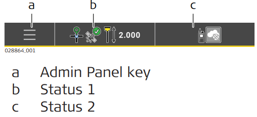
iCON build / iCON build Plus
default display
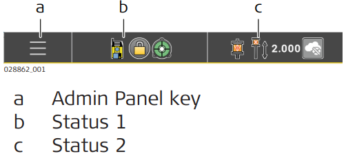
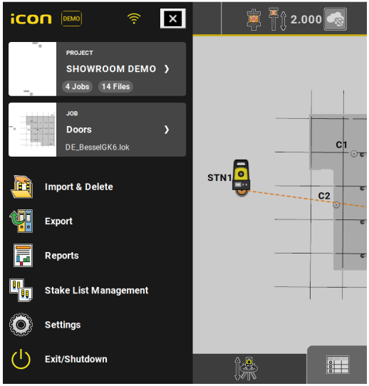
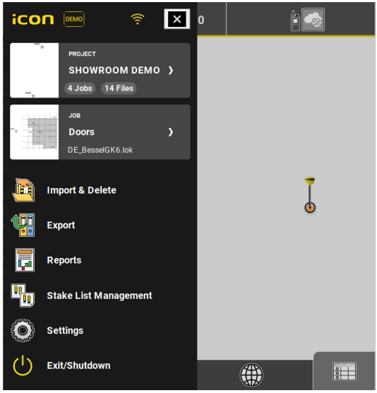
a Admin Panel key

Tap the Admin Panel key to:
- Open the Admin Panel.
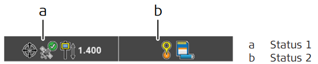
b Status 1
Displays the instrument status.
Tap the Status Bar to get access to more information/functionality.

Availability of information/functionality depends on the connected Total Station and on the display settings.
 |
Select the Measure Mode from: 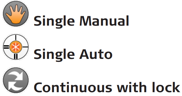 |
 |
Select Visibility settings. Not available for iCON iCR70/iCON iCR80. |
 |
Switch Laser Pointer on or off. |
 |
Switch Guidelight on or off. |
 |
Switch the Compensator on or off. If activated in the User Permissions you can also switch on Formwork Deck Mode when working on unstable ground, where the level gets out of work and back to work at short intervals due to the movement of the ground. Lock on the prism is kept, and as soon as the level comes back in range, meausrements can be continued. This speeds up measuring, but with a lower accuracy of the result. |
 |
Use Hz = 0 to easily set the current orientation as zero orientation. |
 |
Use the Check Setup function to start a Total Station setup check. Only available for robotic/motorised Total Stations and specific setup methods. Needs to be activated in the Setup Instrument wizard. |
 |
Switch Drizzle & Mist Mode on or off. Improves the search and lock behaviour in bad weather conditions. Only available for iCR Total Stations. |
 |
Use Wait & Lock to make the Total Station lock onto the prism when you walk with the prism through the line of sight of the telescope. ☞ Only available for iCR80/iCR80S with an active dynamic lock license. ☞ With an active dynamic lock license Wait & Lock can also be set as an automatic search setting in case of losing the prism. See also: Automatic Search Settings |
 |
Allows for viewing the Station Information details. |
 |
iCON build / iCON build Plus Additional function accessible from Status 1 when using iCON build/ iCON build Plus default settings: The overall Devices Management can be accessed from |
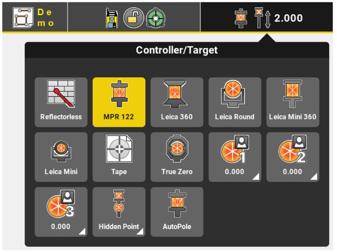
c Status 2
Displays the pole and controller status.
Displays the Leica ConX connection status, if a Leica ConX licence is available.
Tap the Status Bar to get access to more information/functionality.
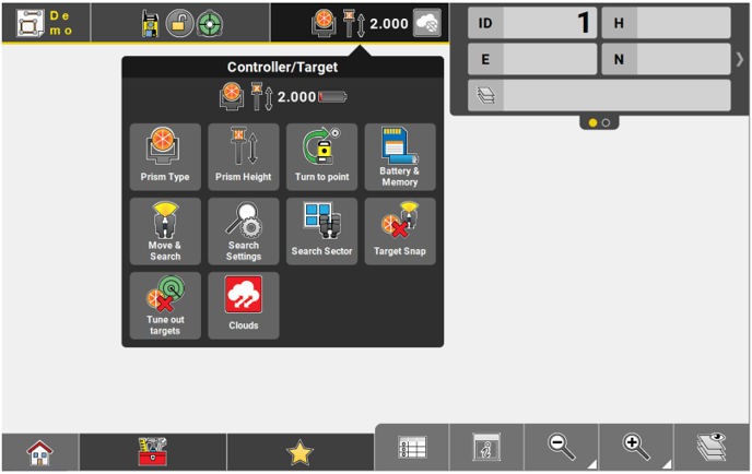
 |
Define Prism Type. |
 |
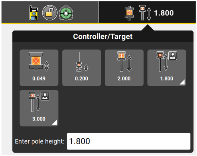
Define Prism Height. |
 |
Use Turn to point to simply select a point and have the Robotic Total Station automatically turned to that point. |
 |
Tap to display battery and memory status. |
 |
Start the Move & Search pilot. |
 |
Prism search controls are found in the Search Settings. |
 |
Use Search Sector to define a sector for the automatic prism search, which helps to reduce prism location time. |
 |
To ban fixpoints from a PowerSearch set Target Snap to On. PowerSearch will then ignore prisms with known position. All prisms used for a station setup calculation and all measured control points are excluded from any PowerSearch. Target Snap can only be used with a iCON iCR60, iCON iCR70, iCON iCR80, TS16, TS60, MS60 and an appropriate license. |
 |
With Tune out targets the LeicaiCON iCR60, TS16, TS60, MS60, iCON iCR80 or iCON iCR70 (with additional licence) starts a scan: the Total Station searches three times the full circle and scans for target points. All scanned targets are included in the Exclusion List. An existing Exclusion List is overwritten. All points within the Exclusion List are excluded for automatic or manual prism searches. |
 |
The overall Clouds Management can be accessed from here. See also: Cloud Settings |
Status bar 
Status bar displays the status of the controller, the connected instrument, position quality information, and information about the current application. It consists of three keys:
| iCON site / iCON site Plus | iCON build / iCON build Plus |
 |
 |
|
a Application key iCON site / iCON site Plus |
Admin Panel key iCON build / iCON build Plus |
|
Displays the icon of the application in use. Tap the Application key to:
 |
Tap the Admin Panel key to:
 |


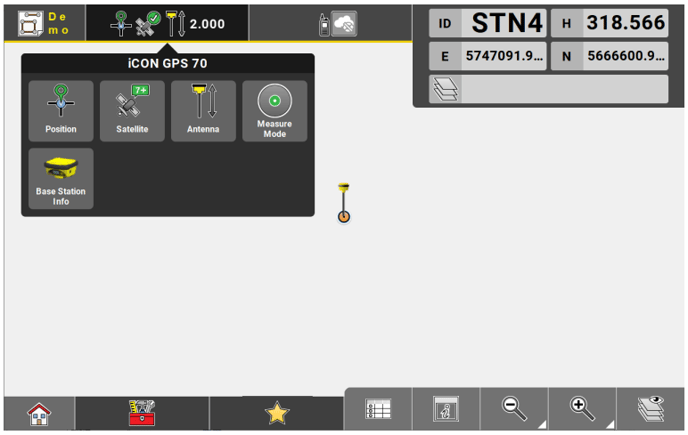
b Status 1
Displays the Instrument/Antenna status.
Tap the Status Bar to get access to more information/functionality.
 |
Tap to display position information and tilt angles. You can activate tilt functionality from here. Tilt functionality is only available for the iCON iCG70 and the iCON iCG160 antennas. |
 |
Tap to displays satellite details. |
 |
Tap to alter the antenna height and to activate tilt functionality. |
 |
Select the Measure Mode, for the instrument used as rover. Refer to How to set the Measure Mode for more information. |
 |
Allows for viewing the Base Station Information details. |
 |
iCON build / iCON build Plus Additional function accessible from Status 1 when using iCON build/ iCON build Plus default settings: The overall Devices Management can be accessed from here. |
c Status 2
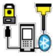
Displays status of communication device.
Displays the Leica ConX connection status, if a Leica ConX licence is available.
Tap the Status Bar to get access to more information/functionality.

Tap to display connection status of:
 |
Radio |
 |
Modem |
 |
PPP |
 |
RTK Bridging |
 |
SBAS |
 |
Bluetooth (if configured) |
 |
Tap to display battery and memory status. |
 |
The overall Clouds Management can be accessed from here. See also: Cloud Settings |
Status bar for internal GNSS
The status bar is only available when the profile for internal GNSS is set up and no other profile is active. Refer to 2.5.6 How to set up a GNSS Profile for the Internal GNSS of the controller .
Status bar displays the status of the controller, position quality information, and information about the current application.
a Status 1
Displays the Controller/Internal GNSS status.

Tap the Status Bar to get access to more information/functionality.
 |
Tap to display position information. |
 |
Tap to display satellites information. |
 |
Tap to alter the controller height. |
 |
Tap to select the Measure Mode, for the instrument used as rover. Refer to 3.6 How to set the Measure Mode for more information. |
c Status 2

Tap the Status Bar to get access to more information/functionality.
 |
Indicates that internal GNSS is enabled. |
 |
Tap to display battery and memory status. |
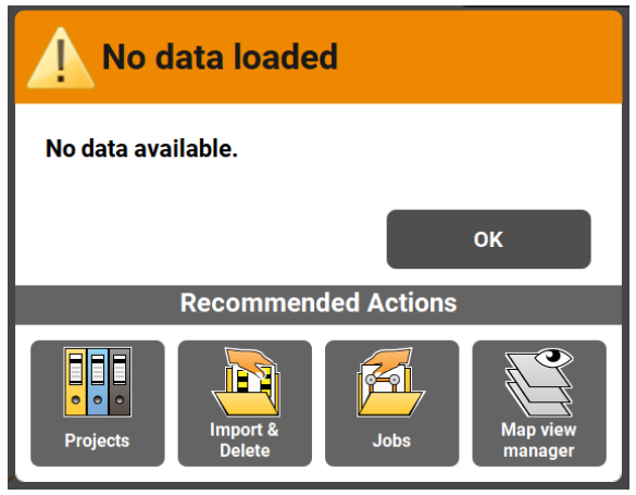
Warning Bar
Displays any issues that are affecting operation.

The number on the Warning bar indicates the total number of warnings that are currently active.
The warning bar can be tapped to display the full message, which:
- displays further information about the problem(s),
- provides navigation to areas where the problem can be fixed.
- By pressing OK without fixing the problem, the warning will be ignored until it is detected again.
Information bar
Displays information that is relevant to the current action being carried out. This will be in one of three forms:
- Guidance text whilst carrying out functions.

- Data from last made measurement.
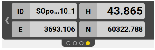
- Directional guidance whilst staking out.
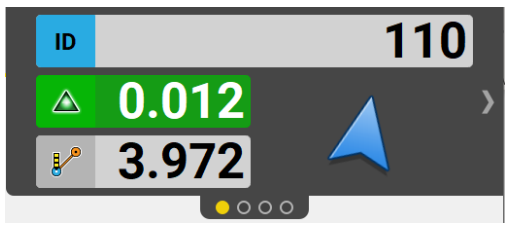
The dots at the base of the Information bar indicate the total number of active pages, which can be scrolled through by tapping on the left-hand side or right-hand side of the Information bar.
Configure the Information bar
The pieces of information shown on each page of the Information bar, can be configured according to your preferences.
Tap and hold for 2 seconds within the Information bar area.
The Info bar configuration screen is displayed where you can define up to six pages, and the amount of information on each page.
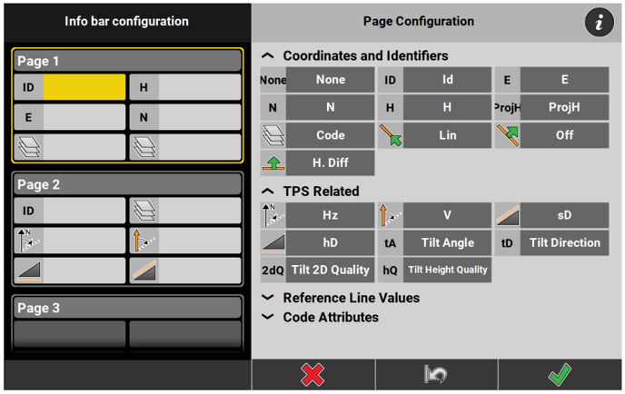
The available pieces of information are grouped in collapsible sub-categories. Availablity of specific information depends on the connected instrument and on the application in use.
To remove a piece of information from any of the pages in the Information bar, select it and tap 'None' from within the Coordinates and Identifiers sub-category.

Depending on the application, different help pictures are available to demonstrate the meaning of the Information bar values. To display the help pictures, tap the info button at the top right corner.
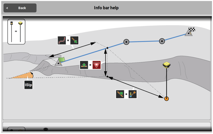
Several help pictures may be available in the Info bar help screen. Scroll down to display all available pictures.
Main map area
The main area of the screen displays all points, lines, and arcs that have been measured, as well as any other data that is loaded to the active job.
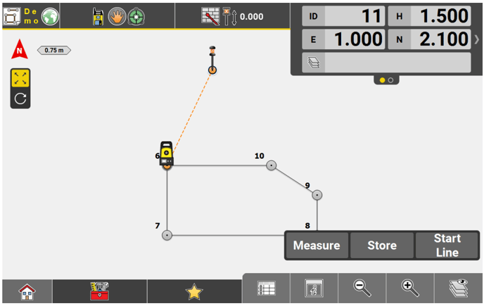
Sample screenshot is taken from iCON site.
Map handler
The Map handler is available whenever the Map screen is open.
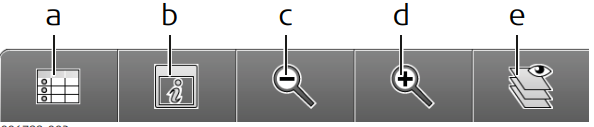
a Point List, including Point search and Point edit
b Continuous Centring, Toggle between Map view and Arrow view, Orientation Configuration, Viewing options, Configure the 5" or 7" multiview display
c Zoom out, Zoom to full extent
d Zoom in, Smart Zoom
e Map View manager
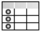 |
Point List, including Point search:
|
 |
View panel, depending on your licence and the active application, following options are available: |
 |
Use Orientation Config to define the view direction of the Map view, the Arrow view and the Bullseye view. |
 |
Turn Continuous Centering of the measured position On or Off. |
 |
Use Viewing Options to configure which attributes are shown for each point in the map. |
 |
Use Limit Box to reduce the amount of visible data in the map view. |
 |
Use Isolate to reduce the number of visible DXF elements or IFC objects by hiding single or several elements/objects of a specific class. For further information refer to: |
 |
Use Multiview Config to switch between single view and split view configurations. |
 |
Use Setup Graphic for controlling the quality of setup constellations. The angles measured between points used to create a station and the station itself are checked during setup and graphically indicated as good or poor. |
 |
Turn on Quick Codes to get the code list displayed on the left-hand side of the screen for quick access. |
 |
Use Perspective View to change from the standard 2D Map view to the perspective 3D view. |
 |
Use to enable the Cross Section or Side View. Side View is available when using Stake Elevation. |
 |
Toggle between Map view and Arrow view in the main map area. |
 |
With Multiview active, use Stakeout Point List to get the points to be staked/laid out displayed. |
|
In applications with many View options, these options are grouped in the following sub categories:
|
 |
Zoom in, Smart Zoom:
|
 |
Zoom out, Zoom to full extent
|
 |
Map View Manager/Layer Manager: Select which data from the active project is displayed and selectable in the Map screen. Refer to Map View manager for more information. |
Measure bar
The Measure bar contains the main commands you will use whilst working, for example Measure, Store, and Code. It consists of between one and three keys, for example:

You can configure the content of the keys according to how you want to work.
Tap and Hold on the Measure bar for two seconds to configure. A configuration menu opens, where different commands can be specified. Available commands differ slightly, depending on the open application.
☞ For some tasks the Measure bar will be automatically altered to allow for the operation to be completed. Once the task is finished, the Measure bar will return to the user defined state.
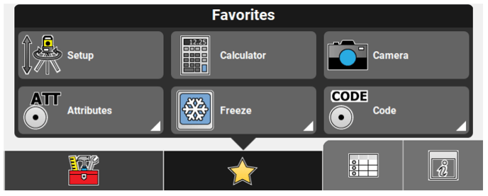
iCON site
Information on Favourites menu configuration:

- Within the Measure bar configuration screen, Tap and Hold any key to add it to the Favorites menu. This provides easy access to the functions you are likely to use regularly, by simply selecting it from the Favorites key
 .
. - To remove a key from Favorites, open the Favorites menu, and tap and hold the relevant key
Function bar
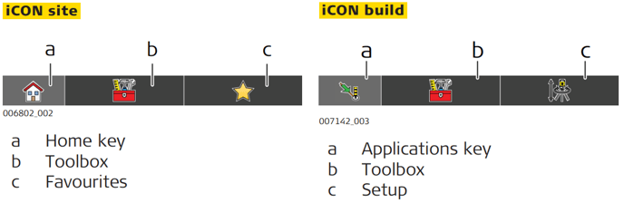
| Icon | Description | |
 |
Home key | Navigates back to the Home screen. |
 |
Applications key |
Displays the different applications available for use. See also: Applications |
 |
Toolbox |
Contains functions relevant to the open application. In applications with many toolbox functions, these functions are grouped in different categories, such as 'General', 'Points', 'Lines' in the Stakeout/Layout Points apps or 'General', 'Road Lines' in the Roading app. Depending on the item currently selected in the map view, the relevant category will be active automatically when the toolbox is opened. |
 |
Favorites - iCON site |
Contains different functions that can be defined according to your requirements. Refer to Measure bar for information about configuring Favorites. By default and always available are:
|
 |
Setup/Coordinate System - iCON build | Navigates directly to Setup - TPS . |
 |
Coordinate System | Navigates directly to Setup Coordinate System - GNSS. |
Wizards
A number of Wizards facilitate common works. Each Wizard leads you through a series of steps, where settings and statuses can be changed.
Example of Wizard Page:
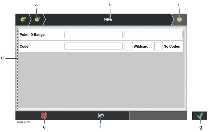
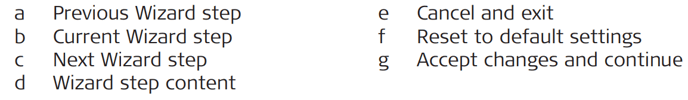
| Element | Description |
| Previous Wizard step | Allows to return to previous Wizard step, if applicable. |
| Current Wizard step | Shows title of Wizard step that is displayed. |
| Next Wizard step | Move to next Wizard step by tapping this key. It is only possible to move to the next step once all required fields are defined in the current setup. |
| Wizard step content | Settings that can be edited by tapping each individual key. |
| Cancel and exit | Exits the Wizard immediately, with no changes saved. |
| Reset to default settings | Resets all changed settings back to default value. |
| Accept changes and exit | Save changes and finish Wizard. Only active once all Wizard steps have been completed. |
Virtual Keyboard
The iCON software includes a keyboard whenever user interaction requires the input of information, like names, login data, descriptions, IDs, values.
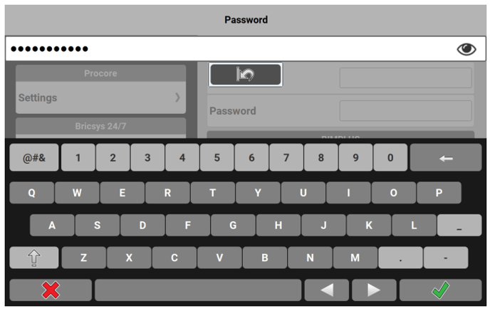
| Key | Description |
|
Toggles between showing or hiding an entered password. By default, passwords are hidden. Tap the icon before entering a password to change its visibility status. |
|
|
Toggles between standard QWERTY keyboard and special characters when necessary. Dot, dash and underscore are available on the standard keyboard as well. |
|
|
Backspace. Tap and hold deletes the whole entry. Alternatively, tap |
|
 |
Move cursor left. Tap and hold moves the cursor to the beginning of the text. |
 |
Move cursor right. Tap and hold moves the cursor to the end of the text. |
For distance values, like instrument or reflector height, you can additionally:
- Switch between distance values in Meter or Feet Fractional.

- When using Feet Fractional switch to using Feet Decimals by tapping the decimal delimiter symbol.

- Toggle between distance values in International Feet or US Survey Feet.