Important notes
➜ Depending on where the prisms/GNSS are located on the machine, different parts of the machine must be measured.
Tower mounted machines: The prisms/GNSS are located on top of the tower. 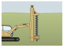
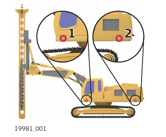
Body mounted machines: The prisms/GNSS are located on the main body of the machine.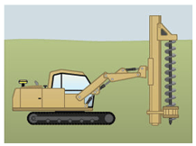
➜ Before starting the machine calibration, ensure that the machine is placed on a flat solid surface where it cannot move or sway. Ensure that the tower is plumbed.
As it is not possible to measure all the required points using one instrument setup, it is required to move the total station to another location during the calibration process.
Before starting any piler or driller calibration
a) Connect to a total station and ensure that it is levelled.
b) Set the tolerances to Precise.
c) Measure at least three to four control points around the machine. Ensure the points are visible from the left, from the right and from the front side of the machine.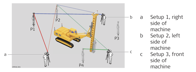
Setting up a tower mounted piler
➜ Place the machine on a solid and flat surface. Do not move the tracks of the machine during calibration.
- Extend the machine (boom and stick) to the maximum horizontal reach if you measure the machine length (ML point).
- Ensure that the tower is plumbed.
- To measure the points visible from the right side of the machine: Set up the total station at the right-hand side of the machine at a distance so that it is possible to measure all the required points (approximatelly 10 - 15 m away).
- Place prisms/tapes at the following points on the machine.
Point C3 located along the center axis of the boom.
Point A located on the hinge joint.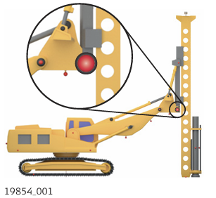
Point TD located at the bottom of the tower.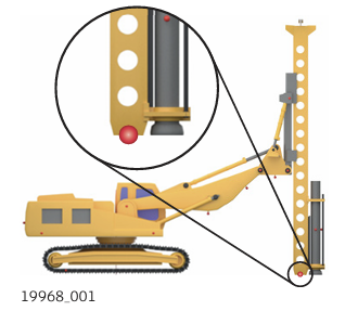
Optionally: Point ML at the back of the machine. Ensure the machine (boom and stick) is
extended to the maximum horizontal reach if this point needs to be measured.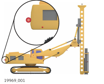
Optionally: Point TC1 at the center of the tool. Use a reflective tape or a mark on the tool.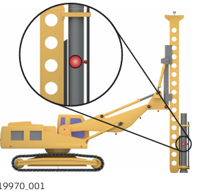
- To measure the points visible from the front side of the machine: Setup the total station at the front side of the machine at a distance so that it is possible to measure all the required points, especially the point at the top of the tower.
- Place prisms/tapes at the following points on the machine.
Point C1 along the central vertical axis of the tower. Use a reflective tape or a mark
on the tower to measure. Ensure that point C1 is aligned with C3.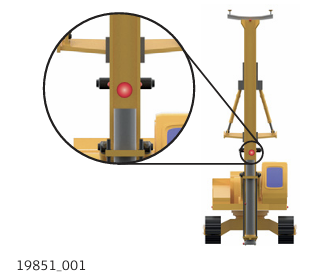
Point C2 along the central vertical axis of the tower. The point must be located at
the top of the tower. Use a reflective tape or a mark on the tower to measure. Ensure that point C2 is aligned with C1 and C3.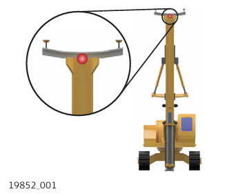
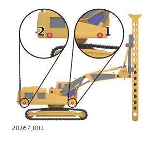
Two prisms on the top of the tower. Pos1 is the left prism (from drivers perspective)
and Pos2 is the right prism. Ensure that the correct prism type is applied to the measurements. Ensure that the correct prism height is applied if the the machine is to be used with GNSS sensors.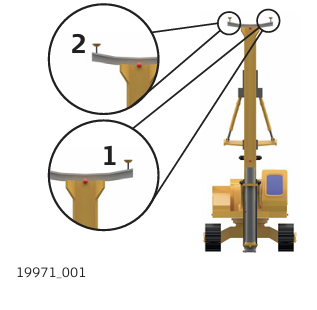
Setting up a tower mounted driller
➜ Place the machine on a solid and flat surface. During the calibration, do not move the tracks on the left-hand side of the machine (where the tool is visible).
- Extend the machine (boom and stick) to the maximum horizontal reach if you measure the machine length (ML point).
- Ensure the tower is plumbed.
- To measure the points visible from the side of the machine: Setup the total station at the side of the machine where the tool is visible, at a distance so that it is possible to measure all the required points (approximatelly 10 - 15 m away).
➜ If the tool is visible from the left side of the machine, setup the total station on the left-hand side of the machine. Otherwise setup the total station on the right-hand side of the machine. - Place prisms/tapes at the following points on the machine:
Point C3 located along the center axis of the boom.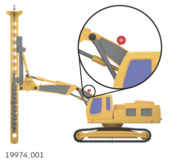
Point A located on the hinge joint.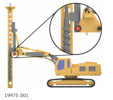
Point TD located at the bottom of the tower.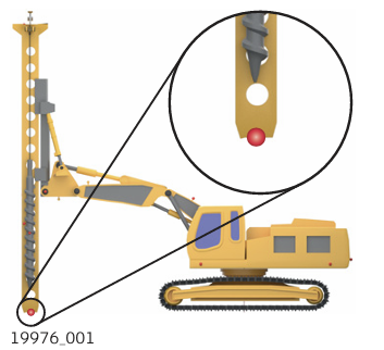
Point TC1 at the center of the tool. Use a reflective tape or a mark on the tool.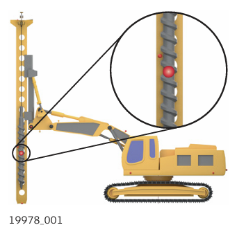
Optionally: Point ML at the back of the machine. Ensure the machine (boom and stick)
is extended to the maximum horizontal reach if this point needs to be measured.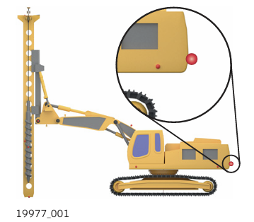
- To measure the points visible from the front side of the machine: Setup the total station at the the front side of the machine at a distance so that it is possible to measure all the required points (especially the point at the top of the tower).
- Place prisms/tapes at the following points on the machine.
Point C1 along the central vertical axis of the tower. Use a reflective tape or a mark on the tower to measure. Ensure that point C1 is aligned with C3.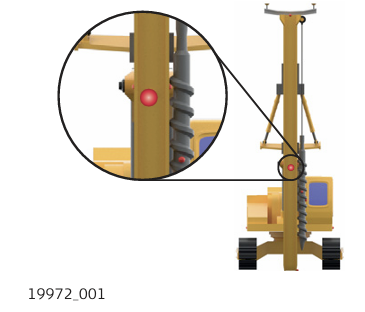
Point C2 along the central vertical axis of the tower. The point must be located at
the top of the tower. Use a reflective tape or a mark on the tower to measure. Ensure that point C2 is aligned with C1 and C3. Ensure that point C2 is aligned with C1 and C3.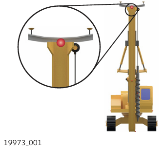
Point TC2 at the center of the tool. Use a reflective tape or a mark on the tool.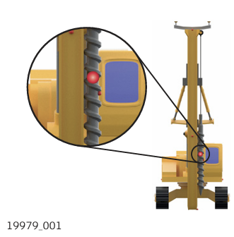
Two prisms on the top of the tower. Pos1 is the left prism (from drivers perspective) and Pos2 is the right prism. Ensure that the correct prism type is applied to the measurements.
Ensure that the correct prism height is applied if the the machine is to be used with GNSS sensors.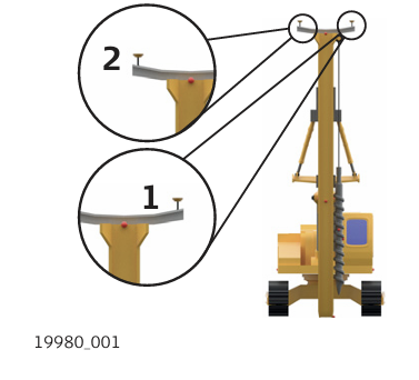
Tower-mounted piler/driller with shortboom
If the boom is too short and C3 cannot be measured, enable the short boom option and measure
the points Ref1 and Ref2 located on the side of the machine. Ref1 is the front point and Ref2 the rear point.
➜ It is important to have the boom and tower aligned with the machine body. The points Ref1 and Ref2 must be also aligned with the boom. 
Setting up the piler/driller Body mounted
- Place the machine on a solid and flat surface. Do not move the tracks of the machine during calibration.
- Ensure that the tower is plumbed.
- To measure the points visible from the right side of the machine: Set up the total station at the right-hand side of the machine at a distance so that it is possible to measure all the required points.
- Place prisms/tapes at the following points on the machine:
Two prisms on the machine body. Pos1 is the left or rear prism and Pos2 is the
right or front prism. Ensure that the correct prism type is applied to the measurements.
Ensure that the correct prism height is applied if the the machine is to be used
with GNSS sensors. If an MPR122 is used, apply 5 cm for the prism height.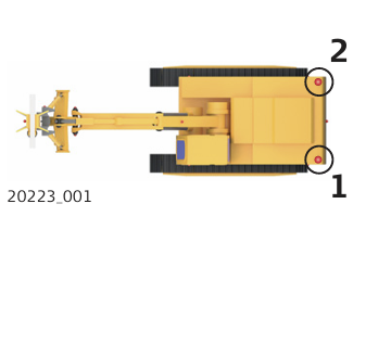
Point C1 along the central axis of the boom.
Point C2, along the central axis of the boom.
Point C3, along the central axis of the stick.
Ensure that C1, C2 and C3 are aligned.
Point A at the boom joint.
➜ If point A cannot be measured directly, enable Hidden Boom Joint option and measure the stick joint at five different position. Refer to 9.5.3 Additional Calibration Options for Excavators .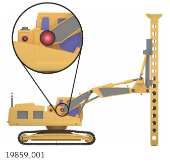
Points B and B2 located at the boom and stick joints.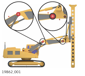
Point B2 is optional, but must be measured when the driller has dual boom.
Point C located at the hinge joint. If a piler has no stick, this measurement can be skipped.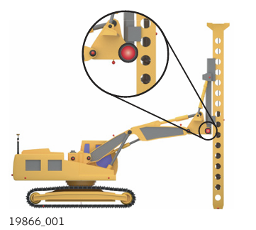
Point TD located at the bottom of the tower.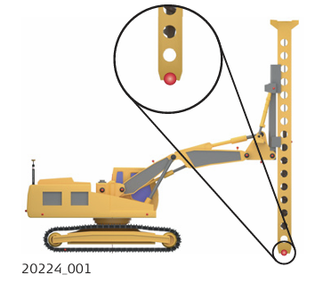
Optionally: Point TU located at the rotation point of the tower.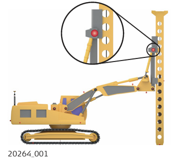
For drillers only: Optionally: Point SL located at the swing rotation center. Ensure that the correct prism type and prism height are applied to the measurement.
➜ When the machine supports swing rotation, ensure that the boom is aligned with the
tracks before starting the calibration.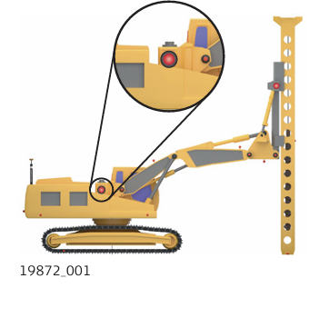
Optionally: Point GH at the machine tracks. Ensure to add the track thickness to the prism
height value.
Optionally: Point ML at the back of the machine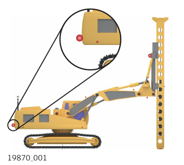
Point TC1 at the center of the tool. Use a reflective tape or a mark on the tool.
➜ For drillers: Point TC1 is mandatory to be measured. If the tool is not visible from
the right-hand side, perform a new setup at the side that can be measured.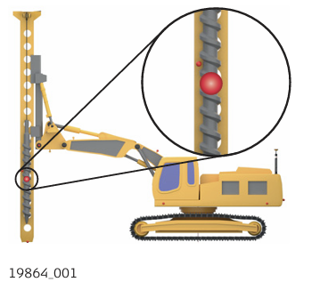
- To measure the points visible from the front side of the machine: Setup the total station at the the front side of the machine at a distance so that it is possible to measure all the required points.
- Place prisms/tapes at the following points on the machine.
For drillers only: Point TC2 at the center of the tool. Use a reflective tape or a mark on the tool.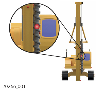
For pilers only: Point TF along the central axis of the tower. Use a reflective tape or a mark on the tower.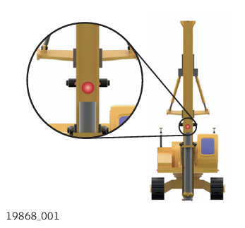
Optional for drillers only: Point HR located along the central axis of the tower. If the towers central axis is aligned with the booms central axis, this measurement can be skipped.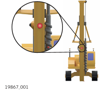
Short boom
If the boom is too short and C1, C2, C3 cannot be measured, enable the short boom option. Measure the points Ref1 and Ref2 on the side of the machine. Ref1 is the front point and Ref2 the rear point.
➜ Boom and tower must be aligned with the machine body. Points Ref1 and Ref2 must be aligned with the boom.
Non-rotating machines
If the machine cannot rotate 360°, enable the relevant option in the configuration screen.
➜ Place the machine on a solid and flat surface. The machine must be levelled and the tower be plumbed.
Machine calibration for pilers/drillers step-by-step
➜ By default, the tolerance setting for a setup is 1.2 cm in position and 1.6 cm in height. For an accurate calibration, stricter tolerances are recommended. Set the tolerances to Precise. Refer to Tolerance settings.
- Measure the control points around the machine. Refer to 6.1 Setup Anywhere with Given Coordinates .
- Open the MC Calibration app.

- Select the calibration method.
The calibration screen is displayed. Refer to section The calibration screen.
➜ Always adhere to the instructions in the display. - Aim the telescope to the target point. Measure and store the target point using the measure bar buttons.
➜ To remeasure points, tap the relevant point in the map screen and confirm the warning message. - Tap Next to proceed to the next calibration step. Follow the on screen instructions.
Aim telescope to target point. Measure and store the target point using the measure bar buttons.
➜ Repeat until all points for the first setup have been measured successfully. You can go back to a previous step to remeasure points. Select Back from the toolbox.
➜ To setup the total station at another location, follow the instructions of the next step carefully. Otherwise the calibration has to be repeated from the beginning. - Before moving the total station, tap the
 Favourites key and access Setup screen.
Move the total station to the second setup point and perform a Coordinates - Anywhere setup by measuring the control points. Refer to 6.1 Setup Anywhere with Given Coordinates . Repeat measuring all other calibration points. - When all points have been measured successfully, the Machine calibration results screen is displayed. To accept, tap
 .
. - Before saving the calibration results, you can set the file location and change the default file name. To store the results onto a connected USB stick, tap Save to and choose USB.
• To save the results, tap .
.
• To cancel the saving process and remeasure points, tap . After successfully measuring points again, execute a recalculation using Calculate from the Toolbox. The new results are displayed.
➜ To display the calibration results again, open the MC Calibration app and tap Calibration Results.