The Importance of Localization in Construction Projects
Localization is a crucial first step when using GNSS receivers on any construction project. It involves converting the GNSS-derived latitude and longitude coordinates into northing and easting values based on the project’s specific design coordinate system. This process ensures the GNSS rover accurately relates global coordinates to the localized coordinate system used for the job.
Understanding Localization and GNSS Rovers
GNSS rovers continuously read latitude and longitude data. Localization tells the rover how these global coordinates correspond to the project’s localized northing and easting values.
Step 1: Obtain Control Point Data
Begin by obtaining a map, text file, or CSV file from your surveyor containing the control point coordinates for the job site. Be specific in your request, ensuring the control points are evenly distributed across the site to provide accurate readings throughout the area. Ideally, you should be able to draw a polygon connecting all control points, with the entire job site falling within that polygon. Avoid clustering all control points on one side of the site, as this can lead to inaccuracies as you move farther from the points.
Step 2: Prepare the Control Point File
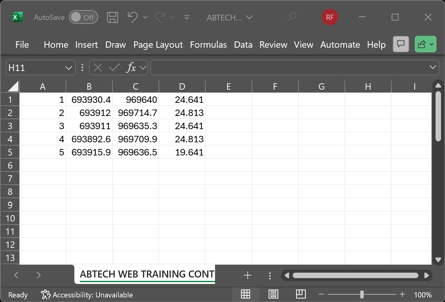
Once the surveyor provides the control points, ensure you receive a file that includes the northing, easting, and elevation of each point. If the surveyor only provides a map, you can manually enter the data into the software or create a text file on your computer. After preparing the file, follow these steps:
-
Open the iCON software and navigate to the home screen.
-
Select the Import and Delete menu.
-
Choose the storage location of the text or CSV file (e.g., USB drive or tablet’s internal memory).
-
Import the file as a "control" file, not reference data, so it is stored under the control section in the layer manager.
-
Check the file format to ensure it matches the expected order (typically, point number, northing, easting, elevation, code). Incorrect formatting can misplace the points.
Step 3: Verify Control Points
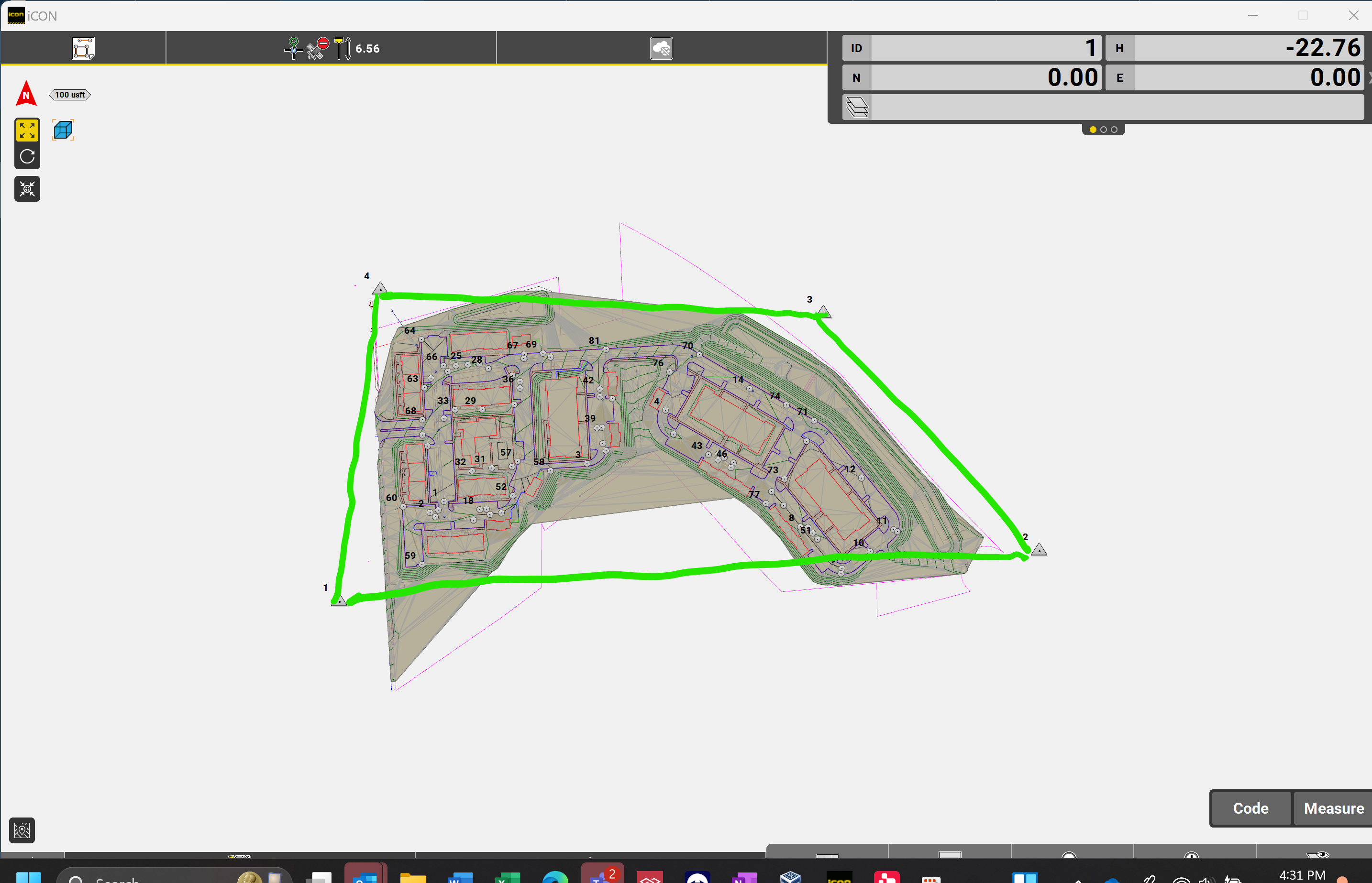
Return to the home screen and enter measure mode to check the map. Confirm the control points are positioned correctly and align with the job site’s boundaries.
Connecting and Configuring the Rover
Ensure your GNSS rover is connected by selecting it from the Device Profiles menu. Verify the rover has a fixed position by connecting to a local base station or network-based station. If you need help setting up the connection, refer to our guide on connecting to a correction network.
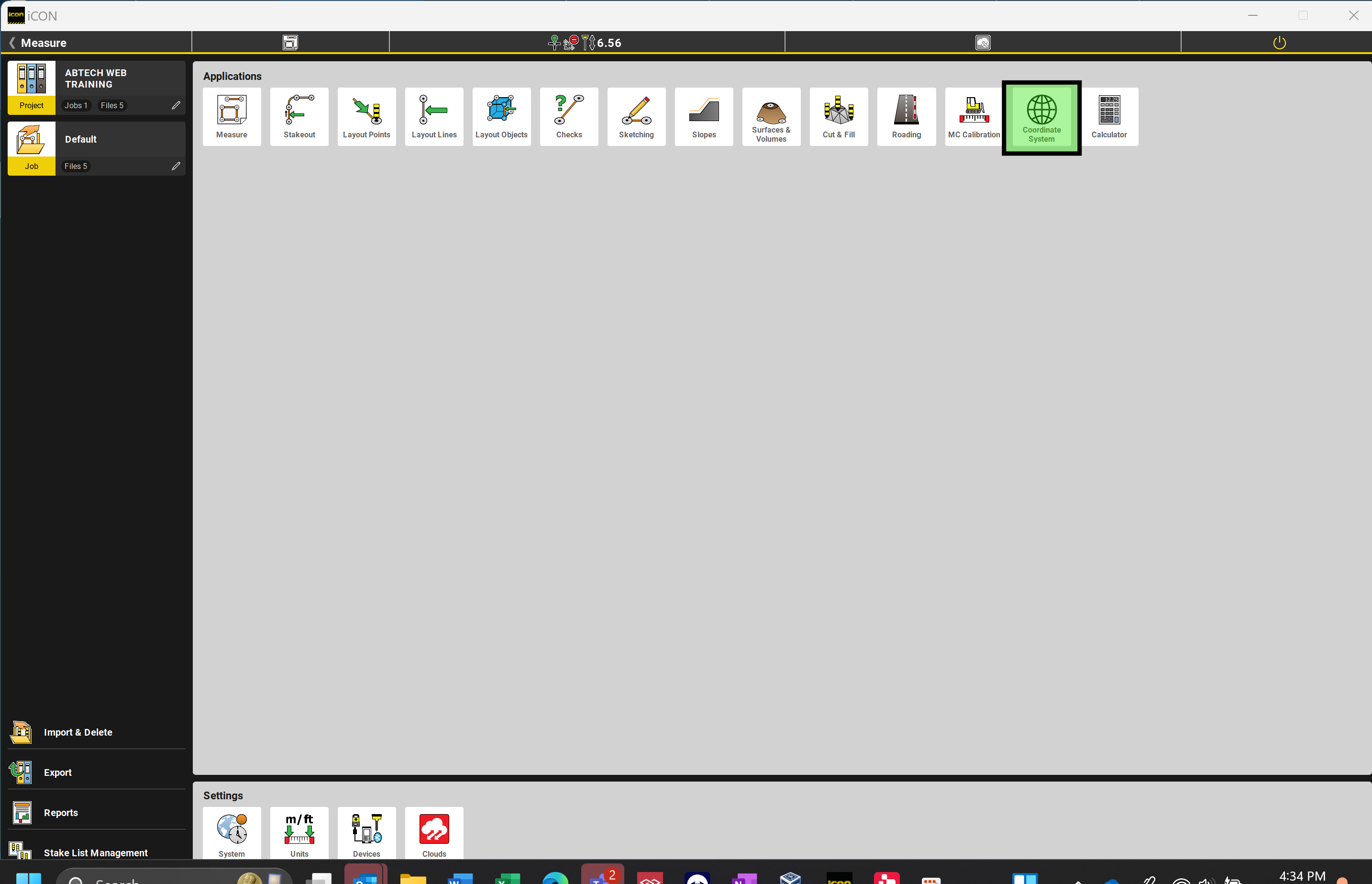
Step 4: Define the Coordinate System
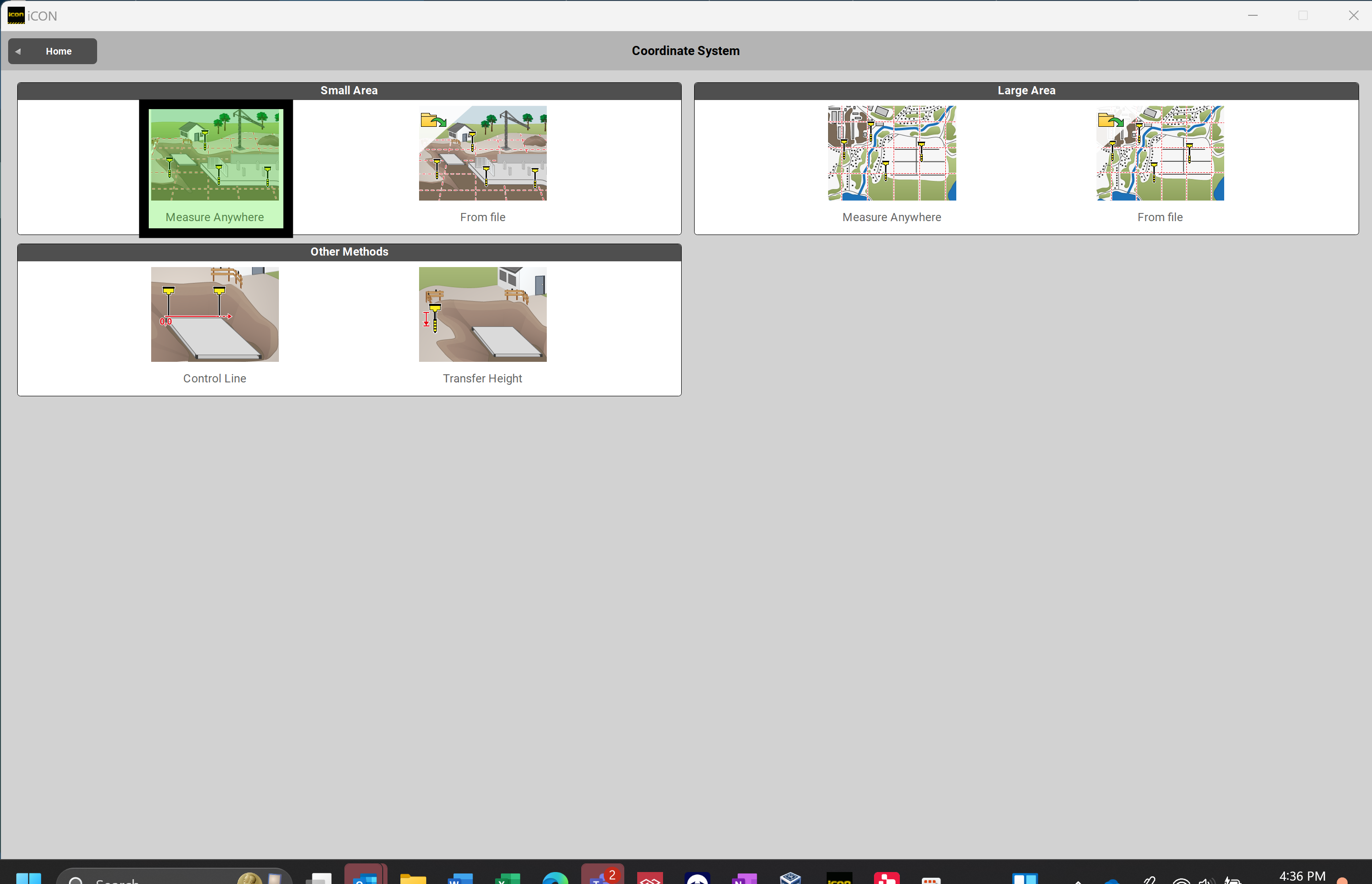
From the home screen, open the Coordinate System application. This menu offers multiple options for defining your coordinate system:
-
Setup Anywhere: Use this option to create a new localization with the rover.
-
Import from File: Use this if you’ve already performed a localization and want to transfer it to other devices.
For small projects, select Setup Anywhere. This will take you to a screen resembling the measure mode interface. The top-right message will prompt you to select the first control point.
Step 5: Measure Control Points
Take your rover to the first control point provided by the surveyor. Set up the rover pole over the point, ensuring it is perfectly level. For best results:
-
Use a bipod or stabilizing legs to maintain the pole’s vertical position.
-
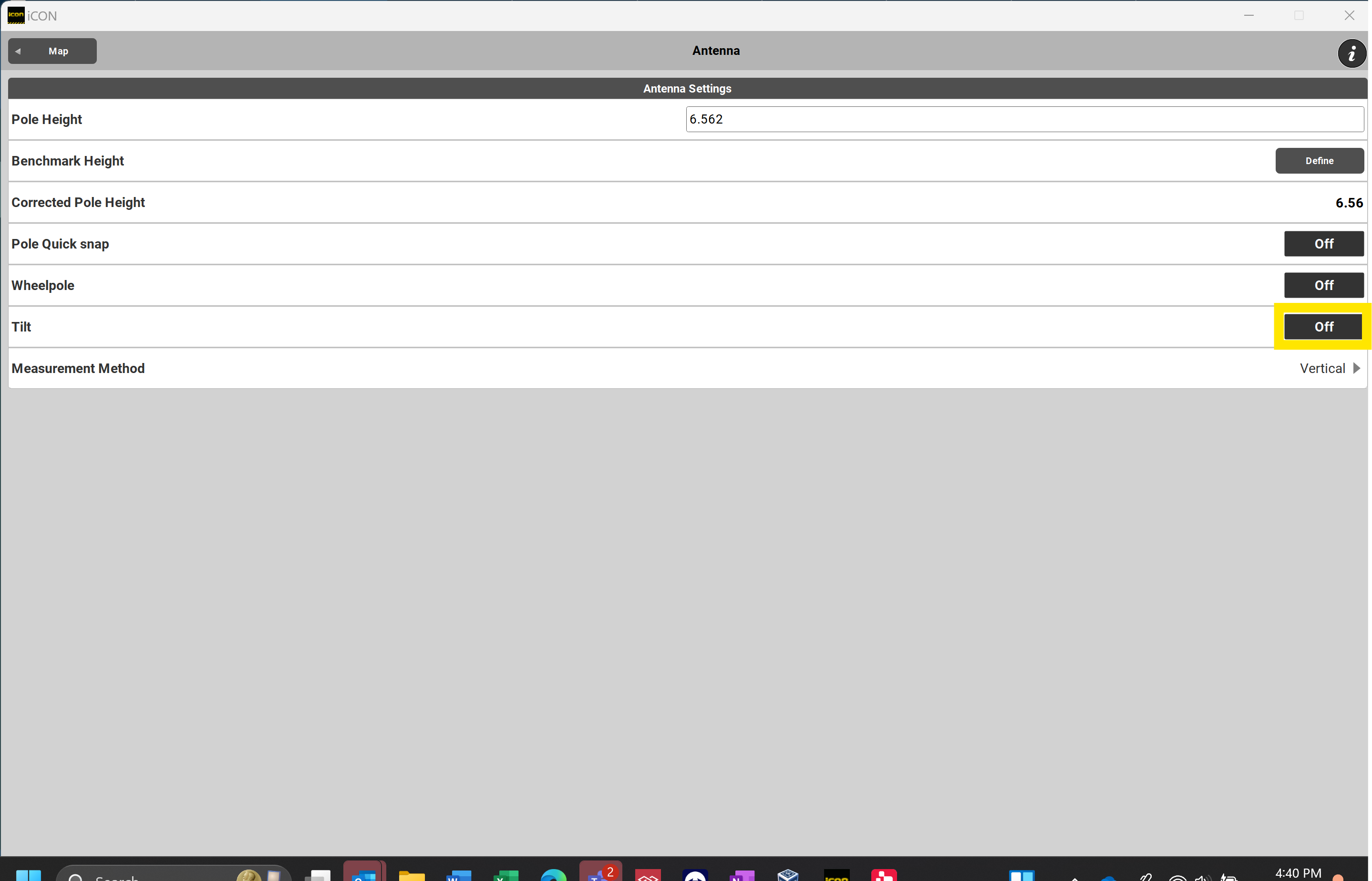
Turn off tilt compensation if using a rover like the iCG70 or iCG160, as tilt compensation can introduce errors. Select Status Bar 1, Select Antenna, Turn Tilt to "Off"

-
Use the bubble to level the pole accurately.
When taking measurements, avoid using the default instant mode, which captures data at the moment the button is pressed. Instead, take an averaged measurement to account for satellite movement and atmospheric variations. To configure this:
-
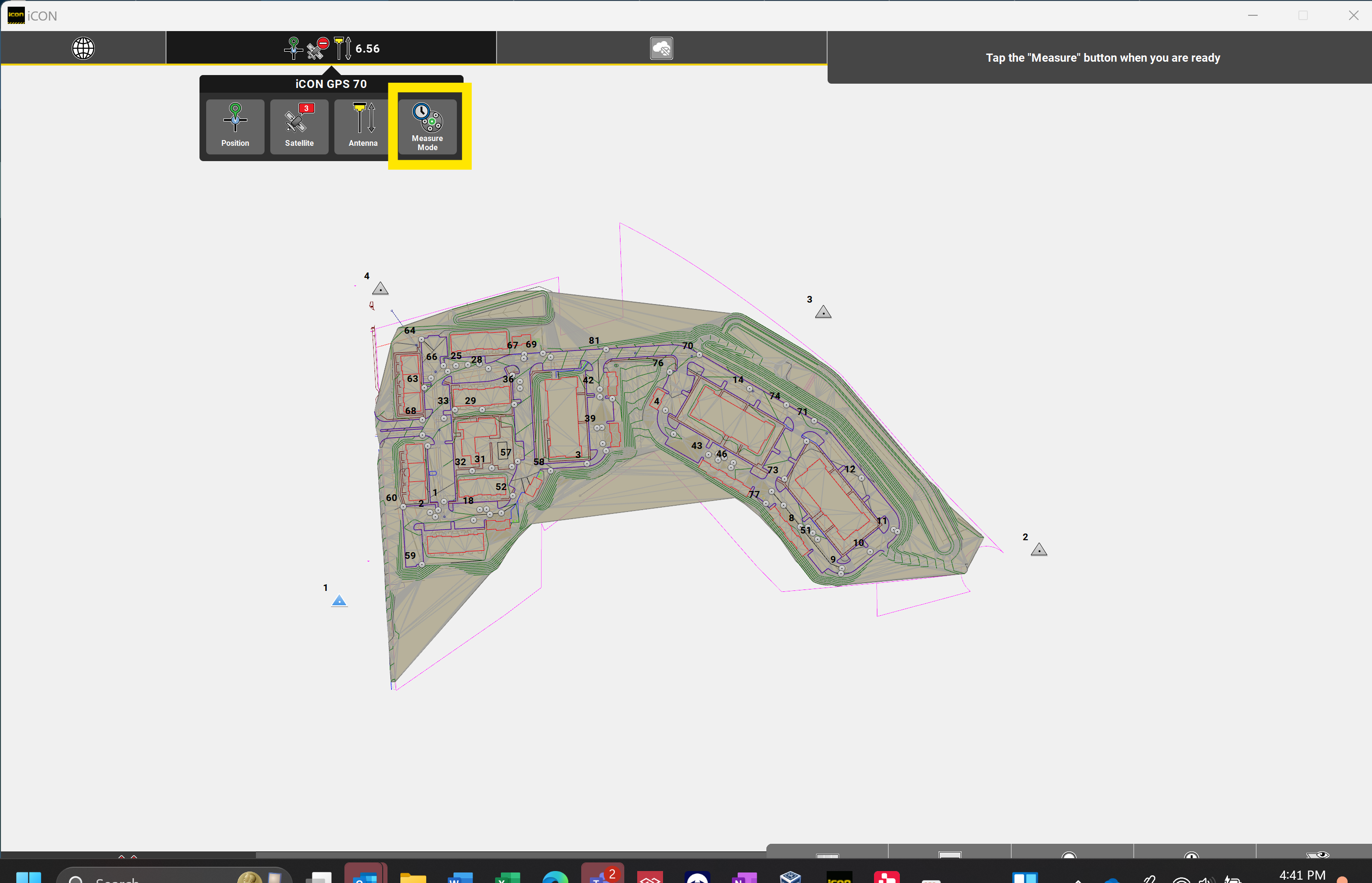
Tap the top-left status bar (Status Bar 1).
-
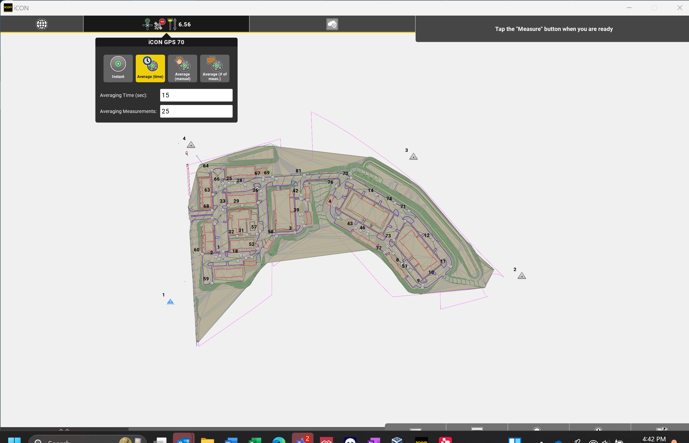
Select Measure Mode and choose one of the averaging options, such as time-averaged measurements or average by a set number of shots. If using a bipod, it is recommended to use the Average (Time) setting. The others are useful if you do not have a bipod available. You can input the amount of seconds in which you would like the GNSS to take an average over.
- Select the control point which you have occupied from the map.
-
Proceed with the averaged measurement to ensure accuracy. You will see in the top right hand corner the time remaining for the measurement, the number of measurements the rover has taken and will average, and the correction quality (CQ) in your specified units.
Step 6: Add Remaining Control Points
After measuring the first control point, proceed to each subsequent control point provided by the surveyor. At each point:
-
Ensure the rover is properly set up and stabilized over the control point.
-
Follow the same procedure for leveling the rover and taking averaged measurements.
-
Verify each point’s location on the map in the software to ensure proper alignment with the project’s coordinate system.
Step 7: Finalize the Localization
Once all control points have been measured:
-
Select the Green Ribbon at the Bottom Left of the Screen to see your residuals.
-
Review the list of measured points to ensure all expected control points are included. If you can tell that one of the control points has a bad elevation or horizontal coordinate, you can remove this from the localization by selecting the horizontal or vertical residual.
-
Select the Green Check Mark to save the localization file to the tablet or export it for backup or use on other devices.
-
Test the accuracy of the localization by navigating to a few known points on the site and verifying the rover’s readings match the expected coordinates.
Large Projects and Geoid Files
For large projects, such as highways spanning multiple miles, consider the curvature of the Earth. This requires including a geoid file in your localization. Detailed instructions for incorporating a geoid file are covered in a separate article.
By following these steps, you can ensure accurate localization for your construction project, setting a solid foundation for precise GNSS-based measurements.