☞ In general, all installation works must be done by a dedicated installation specialist. Please contact the local selling unit or dealer for further information. The installation information within this User Manual is indicated to increase the operators understanding of the system and its maintaining.
☞ Before installation:
• Please observe the maximum vibration and ambient temperature values
indicated in chapter 7 Technical Data.
• Check that all parts needed are delivered.
• It is strongly recommended that you bench test all components before commencing installation on the actual machine to make sure that all components are fully operational.
Installation location
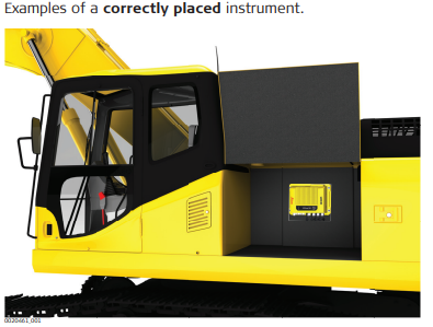
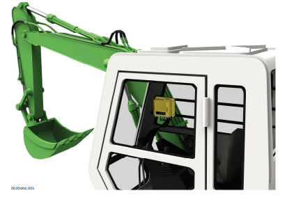
The iCON aps 200 instrument should preferably be installed either inside a compartment just behind the cabin or in the machine cabin itself. If the machine has no space inside a weather proof compartment or cabin, the instrument is to be installed only on components that have no direct connection to the machine tool and/or are positioned separately from the tool or
at locations that lie in the safe area of the mechanically moving components.
Further, the instrument is to be installed so that it is protected from mechanical influences, for example stoning.
☞ The product must not be installed on the tool of the machine and/or on mechanical components that move the tool. Tools include for example bucket of excavator, blade of dozer, screed of paver. Mechanical parts include for example boom and stick of an excavator, hydraulic cylinder of a dozer or tow arm of an asphalt paver. Further, the instrument must not be installed near chassis, chain gear, wheels or on engine components connected to the engine
itself. The cases stated are intended simply as examples.
Installation direction
• For inside assembly, the iCON aps 200 instrument must be installed either vertically with the connectors pointing upwards/downwards or horizontally on a flat plane. A clear view onto the LEDs should be guaranteed.
• For outside assembly, it is strongly recommended to install the instrument vertically with the connectors pointing downwards, in case this is not possible horizontally on a flat plane, but never with the connectors pointing upwards.
Fastening: The iCON aps 200 instrument must have supports beneath all mounting holes and should be fastened with four M6 bolts (or equivalent).
Electrical grounding
The electrical grounds of a Machine may be at different potentials either due to other large current electronic devices on the machine or when different grounds of the machine are isolated in service or welding operations.
Different DC and RF noise may exist at different points in the machine which is out of the control of Leica Geosystems. Such noise may have a negative effect on the satellite tracking performance of the iCON aps 200.
For this reason, it is best that all external antennas connected to the iCON aps
200, including the GNSS antenna(s), radio antenna and modem antenna, are isolated from the machine. This avoids additional ground paths being introduced.
☞ In an ideal installation, with isolated antennas, the connection of the grounding pin on the rear panel of the iCON aps 200 to the machine should not be required.
☞ It is extremely important to disconnect all cables from the iCON aps 200 before starting any welding operations on the machine. Otherwise the instrument may be damaged beyond repair.
Installation of GNSS antennas
For best results, it is recommended to mount the two GNSS antennas according to following guidelines:
• separated as far as possible,
• at approximately the same height,
• with the TNC connectors orientated in approximately the same direction, and
• ensuring an unobstructed view of the sky.
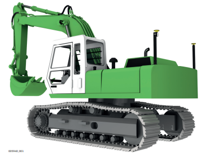
Installation on an excavator:
• Install the two GNSS antennas on the masts in the back of the machine.
• One mast should be placed on each side of the machine. Be aware of heat
from the exhaust.
Installation of external radio: A special bracket for proper mounting can be used.
Installation of antennas for Bluetooth, WiFi, UHF and cellular
• External antennas with a magnetic mount can be used and installed on
the roof of the cabin.
• This will increase the radio signal and therefore the reception of correction signals from a base station or when using an Ntrip solution.
• External antenna needs to be placed with a distance of at least 20 cm to another antenna.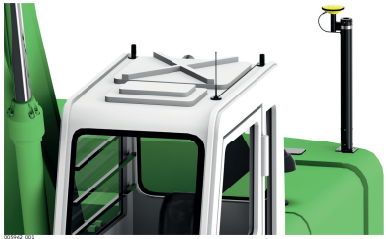
Cable installation
• Ensure that the cables between iCON aps 200 and CGA100 antenna in particular are installed to prevent them from becoming bent and stretched.
• It is recommended to use strain relief brackets.
• Route the cable as directly as possible and avoid crossing cables.
• Be sure not to tie the cables into “hot” hydraulic hoses.
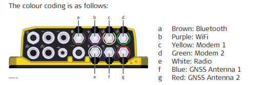
☞ Connecting the wrong antenna to the wrong connector may damage the antennas. In order to minimise the chance of connecting the incorrect external antenna, the four TNC connectors are colour coded. Cables with corresponding colours are available.