Description
| Type/Icon | Description |
|
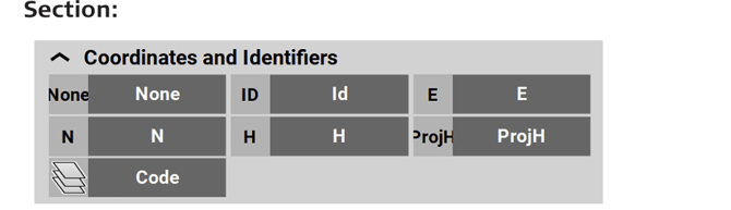
Id
|
Point ID of the current point to record. |
|
E
|
East value at the current target position. |
|
N
|
North value at the current target position. |
|
H
|
Height at the current target position. |
|
ProjH
|
A value set during project creation to define a height shift for measured points in the project. |
|
Code
|
Code/layer for the next point to record. |



| Type/Icon | Description |
|
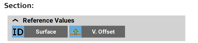
Surface
|
Identifier of the design surface. |
|
VOff
|
Vertical offset value of the defined reference surface. |


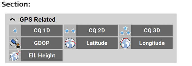
| Type/Icon | Description |
|
CQ 1D
|
Coordinate quality value for the height information at the current position. |
|
CQ 2D
|
Coordinate quality values for the plain information at the current position. |
|
CQ 3D
|
Coordinate quality values for a combination of the height and the plain information at the current position. |
|
GDOP
|
Geometric dilution of precision quality value at the current position. |
|
Latitude
|
Global coordinate to define the north-south position of a point. |
|
Longitude
|
Global coordinate to define the east-west position of a point. |
|
Ell. Height
|
Global coordinate to define the ellipsoidal height of a point. |





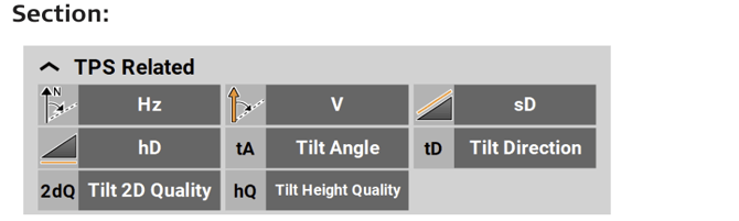
| Type/Icon | Description |
|
Hz
|
Horizontal angle to the current target position. |
|
V
|
Vertical/zenith angle to the current target position. |
|
sD
|
Slope distance to the last point measured. |
|
hD
|
Horizontal distance to the last point measured. |
|
Tilt Angle
|
When using AutoPole: Tilt angle of pole. |
|
Tilt Direction
|
When using AutoPole: Direction in which the pole is tilted, with regard to the compass. |
|
Tilt 2D Quality
|
When using AutoPole: Quality of position measurement. |
|
Tilt Height Quality
|
When using AutoPole: Quality of height measurement. |







| Type/Icon | Description |
|
Cut/Fill
|
Cut/Fill value of the last point measured. |
|
Reference Height
|
Reference height for staking out, that is defined by entering a value or selecting a point or surface. |
|
dHPO
|
Perpendicular height difference from the measured position to the bottom layer of an IFC object. ➜ Only available with an active Scan and Adv. Surfaces licence. |



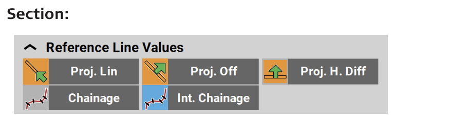
| Type/Icon | Description |
|
Proj.Lin
|
Line value at measured point along the selected reference line. |
|
Proj.Off
|
Offset value at measured point to the selected reference line. |
|
Proj. H. Diff
|
Height difference at measured point to the selected reference line. |
|
Int. Chainage
|
Chainage at the measured point along the selected reference line, without station equation. |
|
Chainage
|
Chainage at the measured point along the selected reference line, including the station equation. |




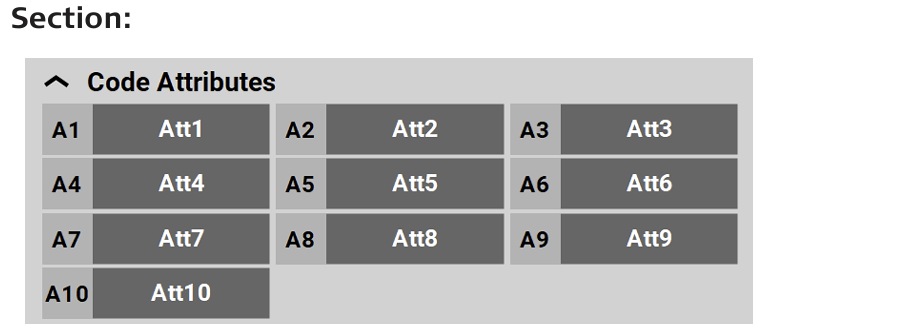
| Type/Icon | Description |
|
Att1 ... Att10
|
Code attributes 1 to 10 of measured point. Up to 25 attributes can be defined, up to 10 attributes can be displayed in the Information bar. |