Jump to:
Importing data to the project step-by-step
Available import formats
Specifically for importing Coordinate Systems
Specifically for importing ASCII files (txt, csv)
Specifically for importing JPG or TIFF files
Specifically for importing DXF files
Specifically for importing IFC files
Specifically for importing data from MC1
Importing data using QR-Scan step-by-step
Exporting data step by-step
Available Export formats
Specifically for exporting data to MC1
Deleting data step by-step
Importing data to the project step-by-step

- Select Import & Delete from the Home screen/Admin Panel.
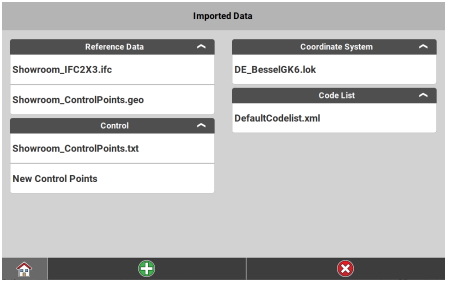
All data that is already loaded to the active project is displayed.
☞ Files that have been imported from and are synchronised with Leica ConX are listed with an indicator. See also: Synchronisation of Projects, Jobs and Data from Leica ConX - Tap
 to import more data.
 - To define the Source to import data, tap the respective button for Internal memory, User Defined, the connected storage device or connected cloud service, such as Leica ConX (if configured).
☞ If you select User Defined, you can import data from any folder that can be found under C:\Users on the controller. When selecting User Defined for the first time, you will be forwarded to the User Defined Path screen. Select the folder where your data is stored and tap to accept your selection. The selected folder will be remembered. Tap and hold the User Defined button in order to select a different folder.
 - Select the type of data to import. Select from:
- Reference Data
- Road Data
- Control
- Point Cloud (if license available)
- Coordinate System
- Code List
- Background Image
- GNSS Profile
- PPP Adjustment
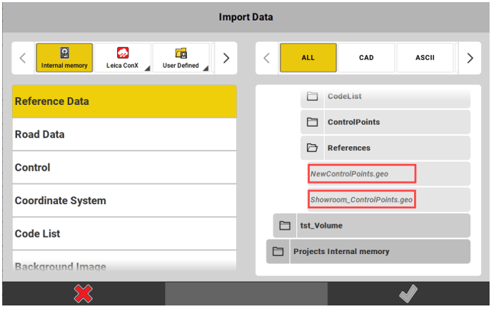
All files that are available for import are displayed on the right side. Files that have already been imported are diplayed in Italic font.
- After selecting the type of data, you can further filter the displayed files by file format, for example DXF, ASCII or PDF. Tap on the name of desired file format.
- Use the tree view on the right side to select the files for import:
- Tap a file name to select a file for import.
- To expand or collapse a folder, tap the folder icon.
- To select or deselect all files within a folder, tap the folder name.
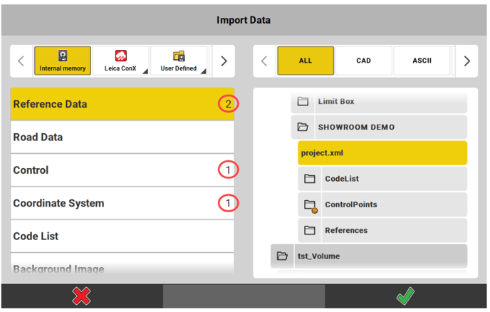
For each data type, the software counts the number of selected files and displays it to the right of the data type name. Collapsed folders that contain selected files are marked with an orange dot.
☞ For certain file types (TXT, CSV, DXF, IFC and others) you can define import settings. To edit the import settings of a file, tap the arrow button . Refer to the following notes for each file type.
- Once the required data is selected, tap
 to import. All selected data is imported, and available in the active project.
☞ Speciality for importing layer-based formats like DXF, DWG, IFC and others: Before the import starts, a file is checked for its size and count of items. If a file is too large, deselect layers to reduce the file size. Then import the necessary data.
Available import formats
| Import data | Import formats |
| Reference Data |
☞ When importing *.xml files, the colours of surfaces, points and lines are imported as defined in the *.xml file and get displayed accordingly in the iCON software.
|
| Road Data | Possible import formats are *.L3D, *.lin, *.lmd, and *.xml (LandXML, HeXML). |
| Control data | Possible import formats are *.txt, *.csv, *.geo, *.gsi, and *.xml (LandXML, HeXML). |
| Point Cloud data | Possible import formats are *.sdb, XML files with multiple *.sdb files, *.pts, and *.E57. |
| Coordinate System | Possible import formats are *.lok, TRFSET.dat, *.xml (LandXML, HeXML), *.dc (Trimble format) and *.loc (Carlson format). |
| Code List | Possible import formats are *.cod, *.xml (LandXML, HeXML) and *.csv |
| Background Image | Possible import format is *.dxf, *.jpg, and *.tiff. |
| GNSS Profiles | It is possible to import iCON GNSS profiles. |
| PPP Adjustment | Possible import format is *.json. |
Specifically for importing Coordinate Systems
Import from controller
- To import a coordinate system that is stored locally on the controller, set the Source to Internal memory, and select the coordinate system from the list below.
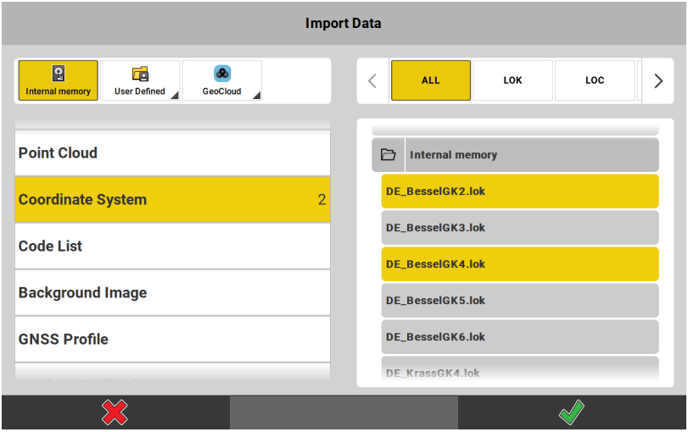
It is also possible to select a coordinate system from a subfolder. - Tap
 to import the selected file and use it with the current project.
Import from reference network
- To use a coordinate system (“transformation set”) that is streamed from a reference network as part of an RTCM3 or LEICA4G message, set the Source to Via Network.
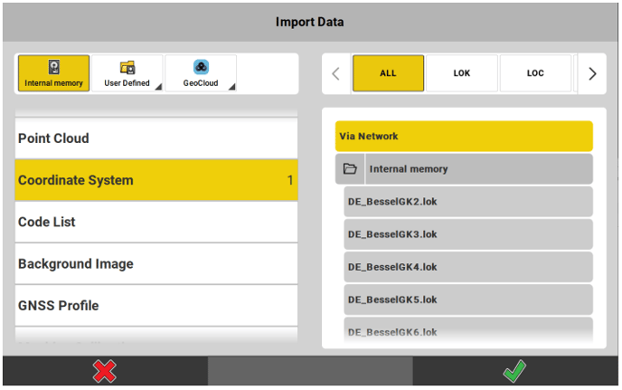
- Tap
 to start receiving the coordinate system.
Import of *.LOC files
- To import a coordinate system stored as *.loc, select file type LOC.
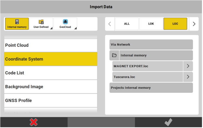
- Tap the arrow
 next to the file to be imported and select an *.lok file for transformation. If needed, select a geoid model, too.
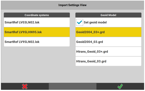
In order to use a geoid model, the respective file(s) must be available in the [CoordinateSystems] folder of the internal memory.
☞ It is up to you to make sure that the correct files are selected for transformation (and geoid separation, if selected).- Tap to make the transformation be calculated and be returned to the Import Data page.
- Tap again to import the selected *.loc file and use it with the current project.
Import of *.DC files
- To import a coordinate system stored as *.dc, select file type DC.
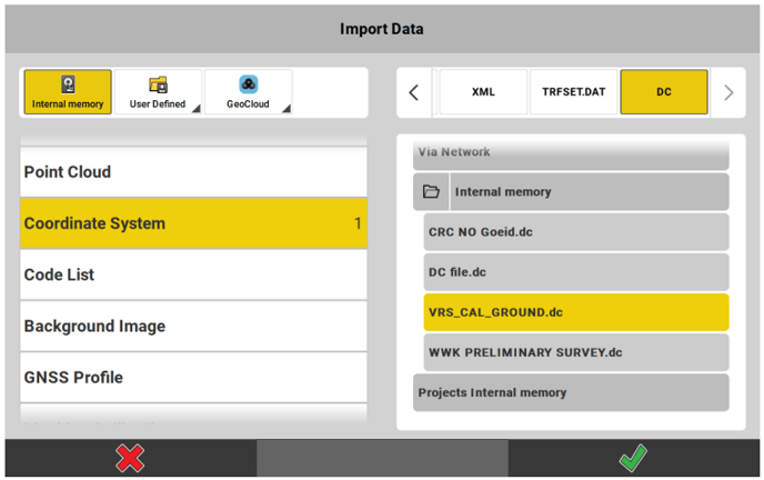
- Tap
 to import the selected file and use it with the current project.
☞ In case the *.dc file has a reference to a geoid, you are requested to select the appropriate model from the list.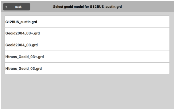
The respective file must be available in the [CoordinateSystems] folder of the internal memory. Without choosing the required geoid model the selected coordinate system cannot successfully be imported.
☞ It is up to you to make sure that the correct geoid file is selected.
Specifically for importing ASCII files (txt, csv)
It is possible to:
- Import ASCII files with up to 10 attribute columns.
- Import ASCII files with different distance units.
- Select the field separator.
- Select between Latitude/Longitude units.
- Skip header rows.
Specifically for importing JPG or TIFF files
Only georeferenced JPG or TIFF files can be imported.
Georeferenced images come together with a world file (*.jgw or *.tfw) that ensures the correct placing of the background image on the map.
The image file and the world file must have the same file name.
Specifically for importing DXF files
It is possible to:
- Import and stake out a Helix data set
- Import 3D solids, but only for visualisation purposes
- It is possible to import splines as a series of lines.
The status of layers set in the CAD software is kept during import:
- Layers that are turned on are automatically turned on
 after import, as
well. - Layers that are unlocked are automatically unlocked
 after import, as
well. See also: Map View manager
Import settings for DXF files
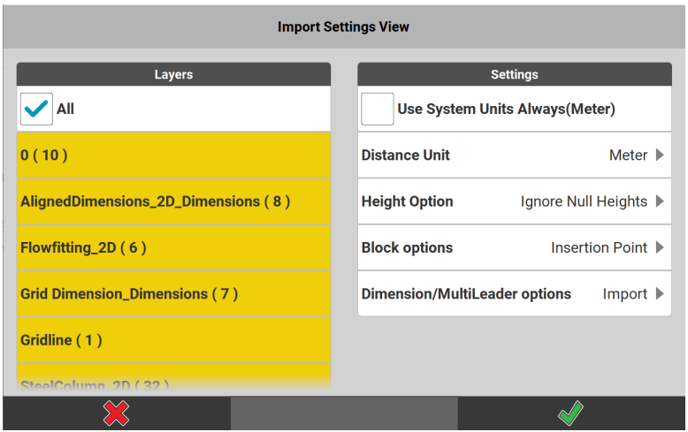
- Select the layers to be imported from the DXF file.
The checkbox All is activated by default.
☞ If all layers are turned off, no data will be imported and no empty file either.
☞ If the DXF file includes circles the circle centre points get saved on a layer of their own, following the naming convention 'Circle1', 'Circle2' etc. - The Distance Unit will automatically be set if a unit has been specified in the DXF file. If not, the system unit will be used.
- Tap the arrow in order to select a unit. If the selected unit differs from the unit in the DXF file a warning is issued when the import is started. For "Feet"/"Inches" select between "Feet Decimals"/ "Inches" or "US Survey Feet Decimal"/"US Survey Inches".
- Select Use System Units Always in order to make system units be used for all imported entities. In brackets you get informed which unit is currently set as system unit. If a unit has been specified in the DXF file, it will be orverridden. The option to select a Distance Unit gets greyed out.
- If the DXF file includes height information, the default setting for import of heights is Ignore Null Heights. Points with height zero will be imported as 2D points.
- Tap the arrow in order to select Use All Heights and make points with height zero be imported as 3D points
- Or select Do Not Use Heights and make all points be imported
as 2D points.
- If the DXF file includes block information, the default setting is to import the Insertion Point as well for every block. The insertion point is stored on an extra layer called 'xxx_Insert' and can be turned on/off via the Map View manager. See also: Map View manager
- Tap the arrow and select Ignore Insertion Point in order to import the DXF file with its block information being kept but the insertion points not being imported.
- Select Explode in order to disassemble the blocks and select/use them in the software. In both cases insertion points of block layers are not imported and layers for insertion points are neither created nor available via the Map View Manager.
- Select Ignore Block in order to make block elements not be imported at all. The layer shown in the Map View manager will be empty.
- If the DXF file includes dimensioning information, the default setting is to import the Dimension/MultiLeader options.
- Tap the arrow and select Ignore in order to import the DXF file without dimensioning information.
- Tap
 to accept.
Specifically for importing IFC files
☞ Importing IFC files requires an active license for at least one of the following applications:
- Layout Objects optional license
- Verification optional license
See also: General Information
IFC files consist of a set of IFC entities (e.g. ifcBeam, ifcWall).
Tap the arrow button to choose which of these entities shall be imported.
After a successful import, a message is displayed informing you about the number of imported IFC entities.
Import of GTP points:
GTP is an object type in Autodesk Revit, which represents a point. The iCON software can automatically detect these objects in an IFC file and import them as reference file points.
Importing Points of Interest:
Points of Interest are points which exist in an IFC file. They are automatically detected from mechanical, electrical and plumbing objects.
Upon import, the IFC file is scanned. If certain objects are detected, for example cable tray hangers or pipe clevis, points are generated.
The points can be used to stake out the objects.
The complex wireframe of these objects is reduced. For example, in the case of air conditioning ducts, the complex mesh is replaced by centrelines and points.
A *.GEO file is created during import. From this *.GEO file, you can create a stakeout list for auto staking.
Import settings for IFC files
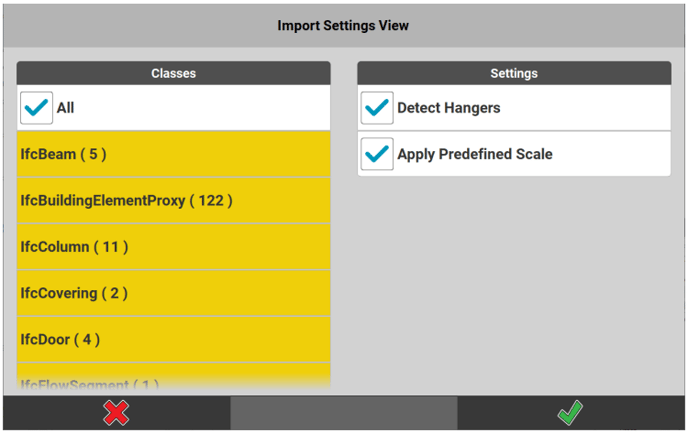
- Select the IFC entities to be imported.
By default, all list items are selected.- To select or deselect all list items, tap All.
- To select or deselect a single list item, tap the requested list item.
- To check the file for hangers during the import, activate the check box Detect Hangers.
- To import IFC files with settings predefined in the model, activate the check box Apply Predefined Scale.
IFC files in US Survey feet can be imported without additional steps in the CAD software. - Tap
 to accept the import settings.
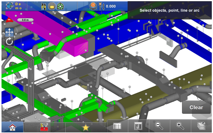
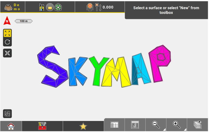
Imported GTP points are shown in 3D in the Map View.
Specifically for importing data from MC1
When Removable Disk ![]() is selected as data source, there is an option to specifically import data from MC1.
is selected as data source, there is an option to specifically import data from MC1.
- Open the directory MC1 Removable Disk.
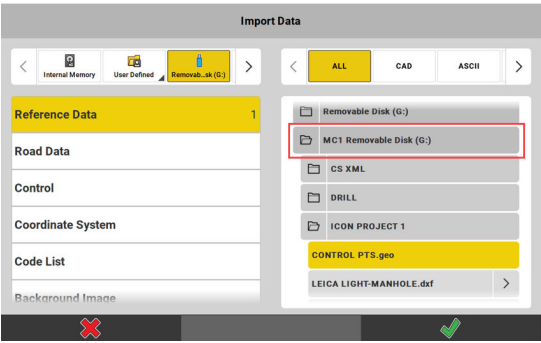
It is possible to import:
• Reference Data
• Road Data
• Control point data
• Coordinate System
☞ You cannot import entire projects from MC1. See also: Projects - Open any of the project folders and select the data to be imported. Multiple selection is possible.
- Tap
 to start importing data.
☞ Within a project folder only those files that are stored in the subfolder [MC1 Data] become available for import. The [MC1 Data] folder itself does not get displayed within iCON.
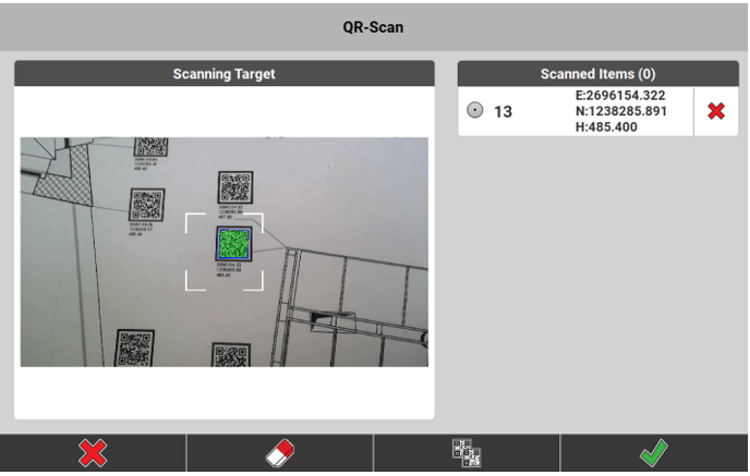
Importing data using QR-Scan step-by-step
Point information can be imported reading a QR-code.
☞ To be able to use the QR-Scan function your entitlement needs to include the "QR Code Reader licence".
☞ iCON supports the following QR-Scan structure:
ID:xx|E:xxx.xxx|N:xxx.xxx|H:xxx.xxx|C:xxxxx|A1:xxx|…
Up to 10 Attribues (A1,...,A10) can be defined.
QR-Scan functionality is available in the applications:
- Stakeout iCON site + iCON build Plus
- Layout Points iCON build + iCON site Plus
- Draw iCON site
- Sketching iCON build + iCON site Plus
- Verification optional license
- TPS Setup
QR-Scan function in New Point tool:
- In the applications Stakeout/Layout Points, Draw/Sketching or Verification open the toolbox.

☞ Toolboxes are organized differently depending on the application that they belong to. In some applications the toolboxes have subcategories.- For details on where to find single functions in the toolboxes refer to:
- Stakeout Toolbox functions/Layout Points Toolbox functions
- Draw/Sketching Sketching Toolbox Functions
- Verification Toolbox Functions
- For details on where to find single functions in the toolboxes refer to:
- Tap New Point

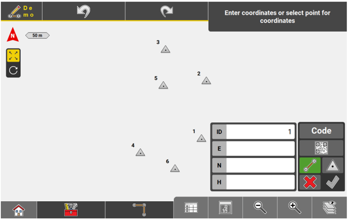
The fields to enter point details are displayed. - Tap
 to start the QR-code scan.
- Use CODE to define and apply a code for every point recorded.
- Enable or disable draw line
 as required. Only available in the Draw/Sketching app.
 - Tap
 to store the scanned point as Control Point.
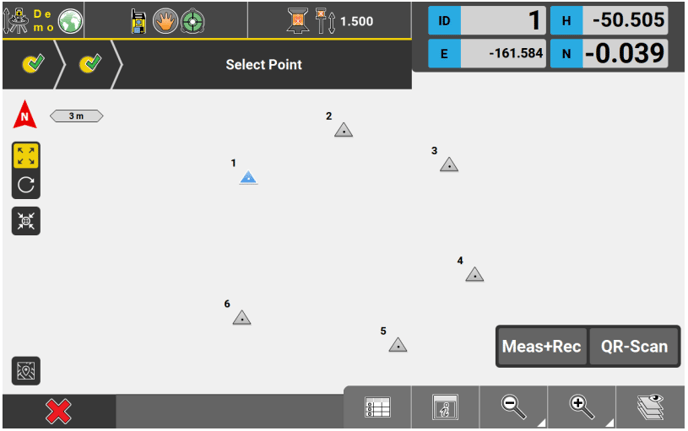
The QR-Scan page is displayed.
- Tap
 to accept.
☞ Tap  to switch from single scanning mode to multiple scanning mode.
In single scanning mode only the code within the white frame will be scanned.
In multiple scanning mode all codes within the camera view will be scanned simultaneously.
QR-Scan function in TPS Setup applications:
☞ For TPS Setup the QR-Scan functionality is available in all coordinate and all height-based methods.
- In step 3 of the setup procedure tap the QR-Scan button.
The QR-Scan page is displayed. - Tap
 to accept.
☞ Tap  to switch from single scanning mode to multiple scanning mode.
In single scanning mode only the code within the white frame will be scanned.
In multiple scanning mode all codes within the camera view will be scanned simultaneously.
☞ In TPS Setup applications a scanned point will be stored as Control Point automatically.
Exporting data step by-step
It is possible to export content to the internal memory, to a connected storage device or to a Cloud server (if configured).
- Select Export from the Home screen/Admin Panel.

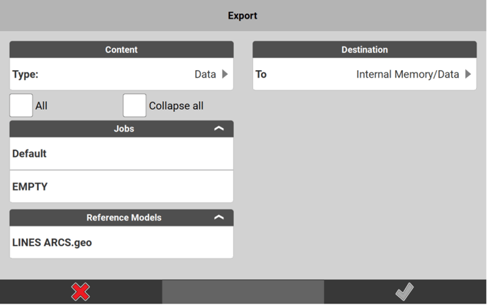
The Export screen is displayed. - To define the content type to be exported, tap the row below the
section Content. Select from:- Data
- Coordinate System
- Code Lists
- Reports
- Projects
- Stakeout Lists
- GNSS Profile
- PPP Adjustment
- Drill Patterns
- Machine Calibration
- TPS Calibration
- Point Cloud
The relevant content available to be exported is displayed on the left side of the Export screen.
- Select the content to be exported. It is possible to select multiple list items. Tap each individual list item or activate the checkbox All to select all items at once.
☞ When exporting Data, it is possible to select a job as well and export a subset of job data this way. - Select a destination to which the exported content shall be stored.
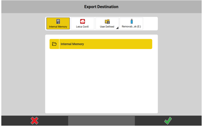
Apart from the Internal Memory, exported content can be stored to a user-defined path, to a removable data storage device or to a Cloud service if included in your licence.
- Specifically for exporting to GeoCloud:
- When exporting Projects, it is not possible to select GeoCloud as export destination. Select a different export destination instead.
- Specifically for exporting to Leica ConX:
- Local projects can be exported as *.db files to existing projects on Leica ConX. Projects that have been imported from Leica ConX can only be synchronised with the respective projects on Leica ConX. They cannot be selected for export.
- Jobs can only be exported as files to a selected project on Leica ConX. Select specific data files instead.
- When exporting data to Leica ConX, optionally select to Export as Avoidance. The selected data will be exported to a file of its own, that can be imported to MC1.
- Specifically for exporting to GeoCloud:
- Tap
 to confirm the selected export destination and return to the Export screen.
 - Select the file format to which the selected data shall be exported.
☞ For some file formats, additional options can be defined. Tap the arrow button beside the format name.
- Specifically for exporting DXF files it is possible to:
- Select a distance Unit for export. The unit information will be written to the DXF file.
- Choose between data being exported as either 2D or 3D.
- Select Stakeout Attributes in addition to Coordinate Attributes to be shown as visible text in the DXF file. Coordinate Attributes are selected by default but can be deselected if desired.
- Export Attributes as block. When this option is activated, then Point symbol and attributes are bundled in the CAD program display.
- Enter a Size for text and symbol. Both will be resized accordingly in the DXF file. Default value is "5", the maximum value is "500". Recommended sizes are dependent on the size of area. For an area of 100 m2 a text and symbol size of "5" is recommended, for an area of 1000m2 preferably use size "40".
- Job data separation. When this option is activated, then the jobname is added to the new layer as prefix.
- Use Description as Layer. When this option is activated, then instead of the code, the code description is exported as a layer.
- Layer colouring is kept when exporting the DXF file and shown correctly in the CAD software.
- Specifically for exporting ASCII files (txt, csv) it is possible to additionally select for export:
- WGS84 coordinates including a column each for the Latitude, Longitude, Ell. Height coordinates plus selection of the desired Latitude, Longitude Units format. Available unit formats are Deg Min Sec (DD.MMSSSSS) or Deg Dec.
- If available in a project, Codes and Code Attributes are automatically exported including up to 10 columns for the code attributes.
- WGS84 coordinates including a column each for the Latitude, Longitude, Ell. Height coordinates plus selection of the desired Latitude, Longitude Units format. Available unit formats are Deg Min Sec (DD.MMSSSSS) or Deg Dec.
- Specifically for exporting DXF files it is possible to:
- To start the export, tap
 .
.
The content is exported as specified.
Available export formats
| Export data | Export formats |
| Data | Possible export formats are *.csv, *.dxf, *.geo, *.gsi, *.xml (LandXML, HeXML), *.kof, *.llc, *.plm, and *.txt. |
| Coordinate System |
Possible export formats are *.lok, *.dc (Trimble format) and *.xml (LandXML, HeXML). Specifically regarding the *.loc file format:
|
| Code Lists | Possible export format is *.xml (LandXML, HeXML) and *.csv. |
| Reports | Possible export formats are *.csv, *.html, *.pdf, and *.txt, depending on the report to export. |
| Projects | Projects are exported as a copy to the selected data storage device. |
| Stakeout Lists | Possible export formats are *.txt, *.csv, *.gsi, *.geo, *.kof and *.dxf. |
| GNSS Profile | Profiles are exported as a copy to the selected data storage device. |
| PPP Adjustment |
Possible export format is *.json. Available for export are the PPP Adjustment files from the active project. PPP Adjustment files can be exported to removable disk for file transfer to machine control systems. |
| Drill Patterns | Possible export formats are *.xml (IREDES standard) for MC1 and *.kof for VisualMachine (kof contains the bottom points of the holes). |
| Machine Calibration |
Machine Calibration files can be exported to removable disk for file transfer to machine control systems. Machine Calibration files are exported with extension ".calibration". |
| TPS Calibration |
TPS sensor calibration reports can be exported to USB stick for documentation purposes. The report is exported with extension ".calibration". |
| Point Cloud |
Possible export formats are *.pts and *.xml. One or more *.sdb files can be selected. When exporting to *.xml, a HeXML file will be created together with an additional folder containing the *.sdb files. ☞ Export to HeXML requires the *.sdb file(s) to contain the necessary setup data. |
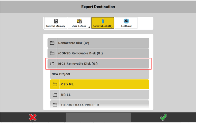
Specifically for exporting data to MC1
When Removable Disk ![]() is selected as destination for export, there is an option to specifically export data for use on MC1.
is selected as destination for export, there is an option to specifically export data for use on MC1.
- Open the directory MC1Removable Disk.
It is possible to export:
• Data
• Coordinate Systems
• Stakeout Lists
• Drill Patterns
☞ You cannot export entire projects for use on MC1. - Tap any project folder to select it as destination for export. Or tap New Project to create a new project folder.
- When you choose to create a new project folder you are prompted to enter a project name.
- In both cases the folder [MC1 Data] is created under the selected or created project folder. In there the exported data will be stored.
- In MC1, when using the sync option "iCON site USB", the software will check for the [MC1 Data] folder and sync all available files.
- The [MC1 Data] folder itself does not get displayed within iCON.
- Tap
 to start exporting data
Deleting data step by-step
- Select Import & Delete in the Home screen / Admin Panel.

All data that is already loaded to the active project is displayed. - Tap
 and select the data to be deleted:
- To select several list items, tap the requested list items.
- To select all list items at once, tap Select all
 .
.
- Tap to delete the selected data.
Tap to cancel.