General description
 * Values to enter during Dimensioning process. For pond inner edge and pond outer edge only the height is entered.
Given:
• Instrument is connected and set up.
• Surface file available in active job.
• Known dimensions of the pond to be established.
➜ Note that main workflow refers to GNSS. For Total Station press Measure, then Store.
Define a Pond fitting in an existing surface step-by-step
- Open the Surfaces & Volumes app.

- Tap the displayed surface to select it.
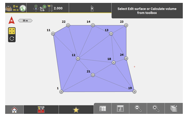
- Select Calculate Pit/Pond from the Toolbox.
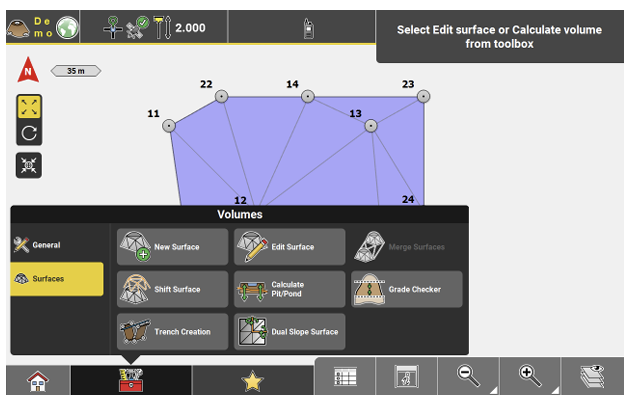
➜ To display different surfaces use Map view manager.
-
 Select the pattern according to your needs. During first-time use, only the Default Pattern is available.
 -
 Now dimension all necessary elements, as shown in the illustration before:
• Define length and width of the pond floor. Enter a relative height value for each of the four floor corner points separately. These heights can vary.
• Enter offset value to the floor lines at . This value is the distance from the floor lines to the pond inner edge.
• Enter a relative height value for the pond inner or pond outer edge. The same height is applied to all eight corner points.
• Define the berm width at .
.
• Define the outer berm slope angle at .
. -
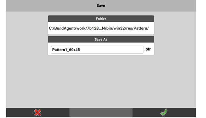
After defining all these values, you can save this pond as a user defined pattern. Tap Save, enter a name and tap . In this case, the software automatically proceeds to the next step.
Otherwise tap the next Wizard step to proceed.
 - Define where to place the pattern at. Pick the line that is used as insertion line.
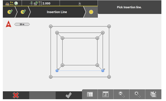
- Proceed to the next step to apply the pattern:
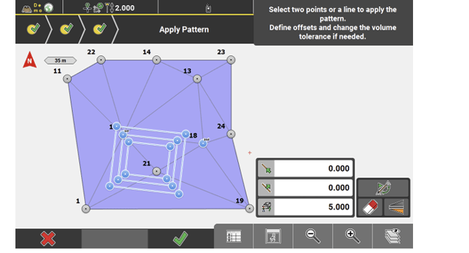
• Select two points or a line as the reference line. If needed, use to switch the start point and end point of the active line.
• Use to flip the pattern across the reference line.
• Enter an offset value along the line at and offset value to
the line at , if needed.
• Define the volume calculation tolerance at . The smaller this value is, the longer the calculation needs.
• When finished, tap to accept.
 - Enter a name for the surface in the next screen, and tap
 to save. Then enter a name for the pond geometry and tap
  to save.
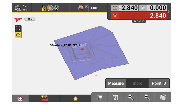
 - In the final screen, the newly created pond is shown applied to the selected surface.
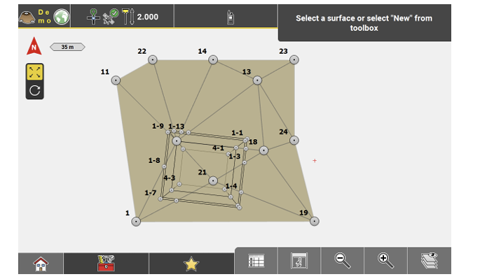
➜ The newly created surface, including the pond, can now be used for staking out, but the data can also be exported for machine use.
➜ Example of the surface with pond, used in Cut & Fill.