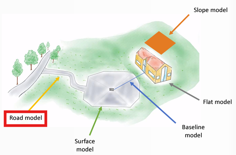
Leica MC1 allows users to create models with the Create Model Application. This article offers a step-by-step guide to create a Road Model, which will apply a defined cross section to a specified alignment. This is particularly useful for not only creating construction roads, but you can also use it to create swales for draining and trenches.
Creating a Road Model
Step 1: Accessing the Create Model Application
Navigate to the Home Screen.
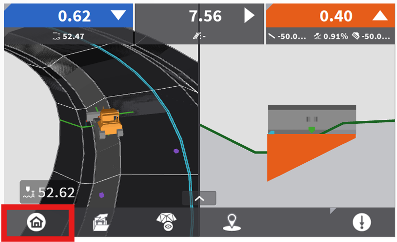
Select Model Options.
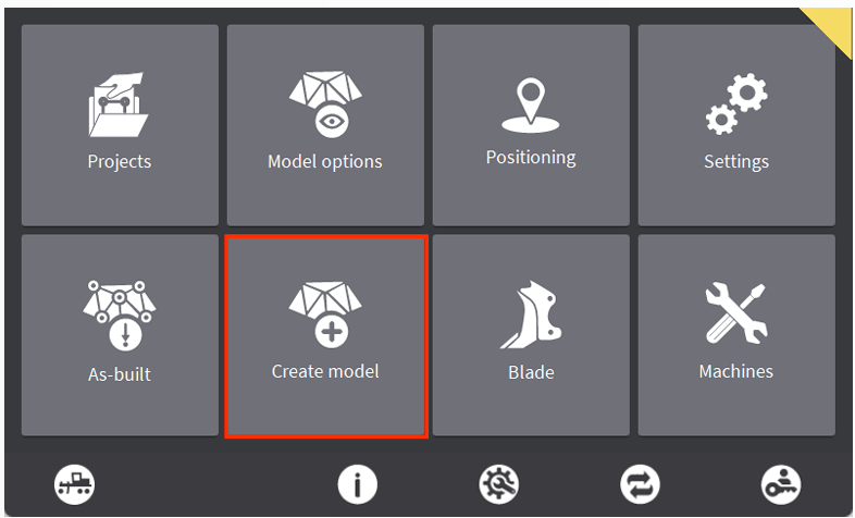
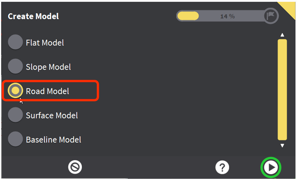
Step 2: Configuring the Road Model
Select Road Model then hit the Arrow to proceed.
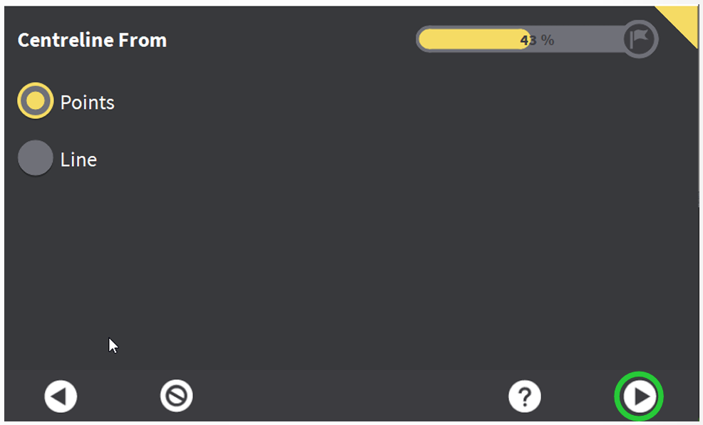
Define the Centerline for your road. If you are using this application to create trenches for a utility, you can use the polyline for the utility as your centerline. You can also manually log points to create your centerline.
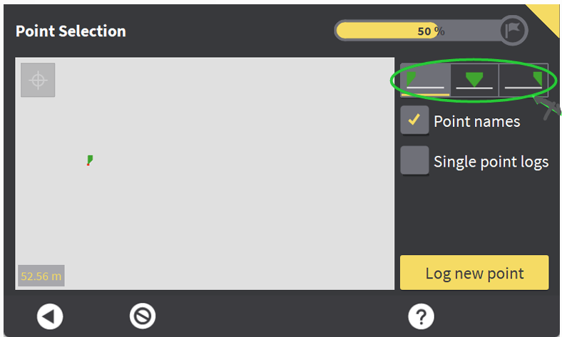
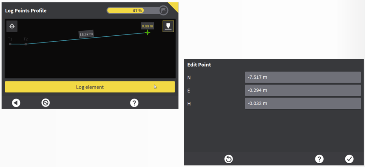
Centerline from Points: Select the Tool Point position you which to use (left, center or right side of bucket). Touch the tool point to the start of where you want your road model and hit Log New Point. Continue down the road logging points at each location where the road will make a bend. After all points have been logged, select each point in order on the Point Selection Screen then hit the arrow to proceed.
The following page will show a profile view of the alignment. If you press and hold on any individual point, you can manually edit the point Northing, Easting or Elevation. Proceed to next step by hitting the arrow after selecting the line.
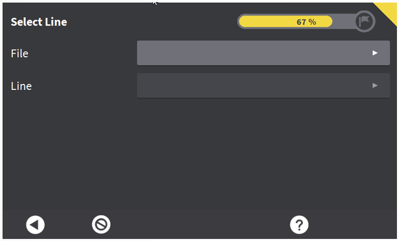
Centerline from Line: To define a centerline as an existing line within a project, select the file in which the line is contained, and then select the line from the drop down. Proceed to next step by hitting the arrow after selecting the line.
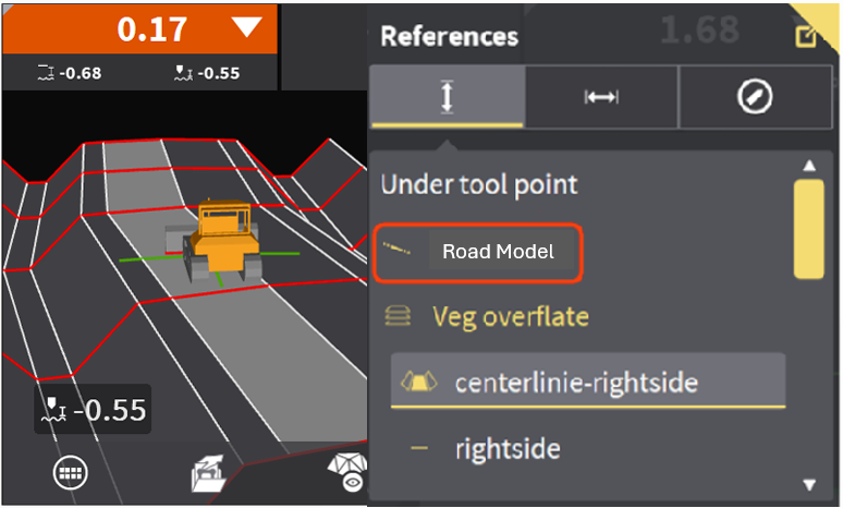
Pro-Tip: If unsure which line number is desired, in the dig/grade screen, if you zoom in and hold your finger over the line you wish to use, the References menu will open up, and the first line you see listed will be the one you want as this is closest to where you pressed your finger.
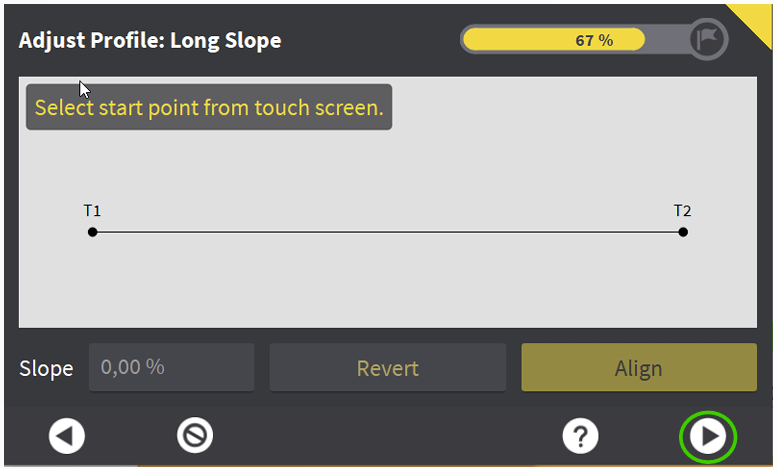
Adjust the Long Slope of the alignment. This will be pitch of your road/swale/trench. You can manually adjust the slope of each segment between points which were logged, or you can hit align which will interpolate the slope between the start and end point for one consistent slope. Hit arrow to proceed.
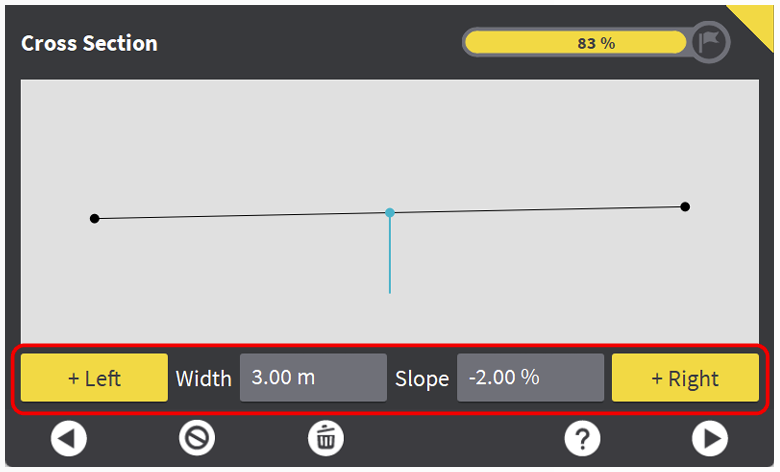
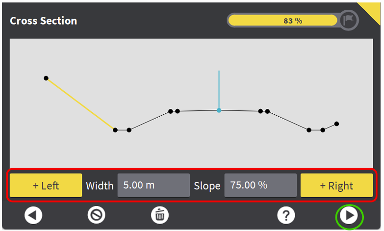
Define the Cross Section to apply to your road Centerline. You manually add "lanes" to the left and right of the centerline. The lines are defined by a width and a slope.
The visual below shows adding various widths and slopes to the cross section to create a two-lane road with a shoulder and swale on each side.
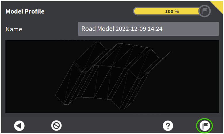
Provide a Name for the Road Model. Hit the Flag to proceed.
Hit the Check to complete the Create Model Wizard.
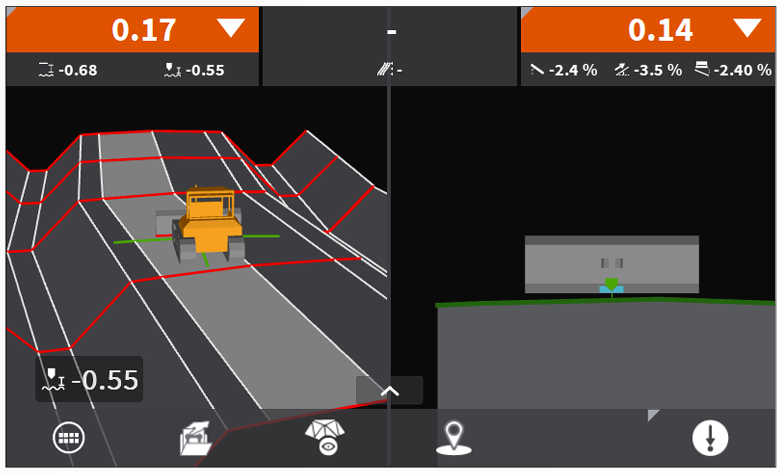
Step 3: Using the Road Model
The Road Model works the same as any other Height Reference. Hold your finger on the screen to open up model selection. You can now switch back and forth between Height References on the fly.